Combined water surface slag catch net and slag catch method

A combined and net-based technology, which is applied to the cleaning of open water surfaces, water conservancy projects, construction, etc., can solve the problems of high cost and low efficiency of slag removal, and achieve the effects of low cost, improved efficiency of slag removal, and convenient recycling.

Active Publication Date: 2019-03-19
钟永
View PDF6 Cites 0 Cited by
  • Summary
  • Abstract
  • Description
  • Claims
  • Application Information

AI Technical Summary

Problems solved by technology

Two ships cooperate to remove slag from the lock to the downstream, etc. The efficiency of slag removal is low and the cost is high

Method used


Image

  • Combined water surface slag catch net and slag catch method
  • Combined water surface slag catch net and slag catch method
  • Combined water surface slag catch net and slag catch method

Examples


Embodiment 1

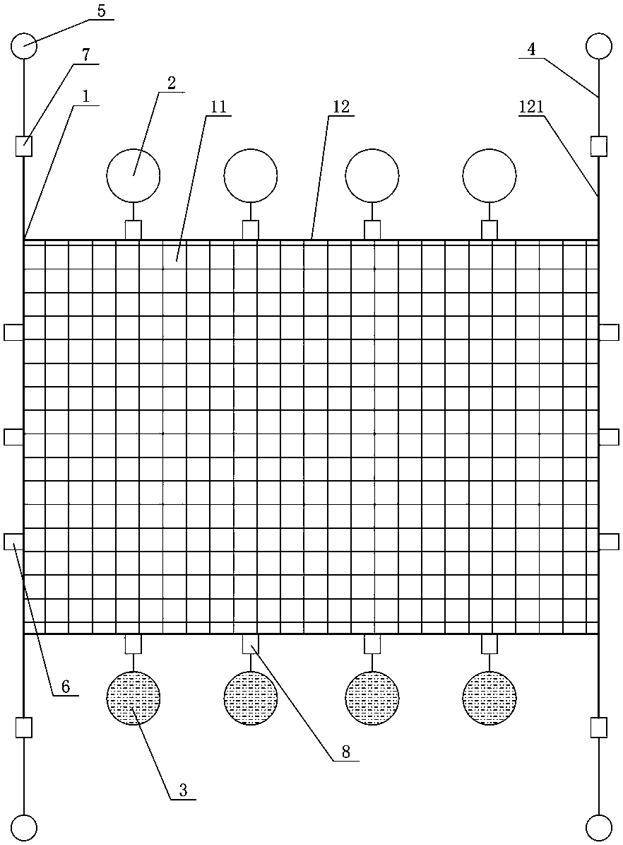
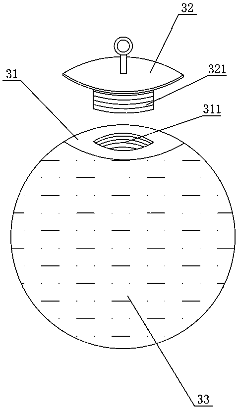
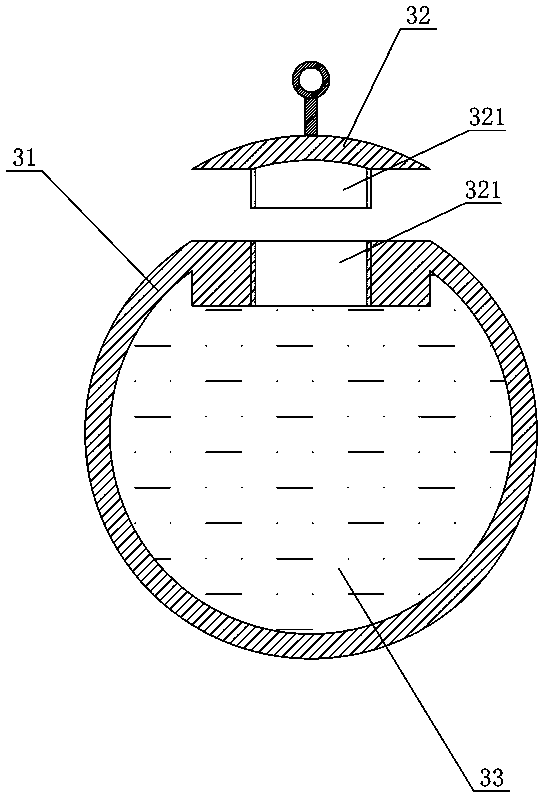
[0034] Figure 1 to Figure 5 It shows the first embodiment of the combined water surface slag catcher net of the present invention, the slag catcher net includes at least one net body 1, and the net body 1 is arranged with a plurality of first floating balls 2 at intervals on the top edge, each first The floating ball 2 is detachably connected to the top edge of the net body 1, and the bottom edge of the net body 1 is arranged with a plurality of sinking balls 3 at intervals, each sinking ball 3 is detachably connected to the bottom edge of the net body 1, and the net body 1 is placed Both ends of the side are detachably connected with traction ropes 4 , and the ends of each traction rope 4 are equipped with second floating balls 5 , and a plurality of first shackles 6 are arranged at intervals on both sides of the net body 1 . When using, calculate the area of ​​the required net body 1 according to the area of ​​one slag catcher. When the slag catcher area is smaller than the...

Embodiment 2

[0043] Such as Figure 6 As shown, the second embodiment of the combined water surface slag-catching net of the present invention is basically the same as that of Embodiment 1, the only difference being that the slag-catching net is formed by connecting two net bodies 1 through the first shackle 6 , can be applied to the situation where the slag catch area is large at one time.

[0044] In other embodiments, the first shackles 6 are arranged at the ends of both sides of the mesh body 1. When two mesh bodies 1 are connected, a rope body is used to alternately pass through the sides of the two mesh bodies 1 in an S shape. Bundling is formed, and then secondary fastening is formed through the first shackle 6 at the end, which further improves the connection strength on the one hand and facilitates disassembly on the other hand.

[0045] Such as Figure 7As shown, the flow chart of the slag-catching method of the present invention is carried out with the above-mentioned combined...


PUM


Abstract

The invention discloses a combined water surface slag capturing net and a slag capturing method. The slag capturing net comprises at least one net body; multiple first float balls are arranged on the top edges of the net bodies at intervals; all the first float balls are detachably connected with the top edges of the net bodies; multiple sinking balls are arranged at the bottom edges of the net bodies at intervals; all the sinking balls are detachably connected with the bottom edges of the net bodies; two ends of two side edges of the net bodies are detachably connected with traction ropes; second float balls are respectively mounted at the ends of all the traction ropes; and multiple first unloading buckles are arranged at two side edges of the net bodies at intervals. The slag capturing method comprises the steps of: (S1) assembly of the slag capturing net; (S2) sinking of the slag capturing net into water; (S3) fixation of the slag capturing net; (S4) traction for slag capturing; (S5) slag packing; and (S6) taking of slag ashore. The combined water surface slag capturing net and the slag capturing method have the advantages of low cost, wide application range, capability of recycling and high slag removing efficiency.

Description

technical field [0001] The invention mainly relates to the upstream slag removal technology of a power plant, in particular to a combined water surface slag catcher net and a slag catcher method. Background technique [0002] The scum accumulated in the upstream of the hydropower station before the sewage interception discharge has been accumulated all the year round. The scum has been cleaned by the flood sluice during the flood season, the flood sluice inspection gate overflow during the non-flood season, and two ships working together to remove the scum from the ship lock to the downstream approach channel. [0003] The slag flushing effect of the flood discharge sluice during the flood season is remarkable, but only when the flow into the reservoir at the end of the flood is relatively large. In non-flood season, the risk of damage to the overflow surface by the overflow of the maintenance gate of the flood discharge sluice increases. The efficiency of cleaning slag fro...

Claims


Application Information

Patent Timeline
Patent Type & Authority Patents(China)
IPC IPC(8): E02B15/10
CPCE02B15/10
Inventor 钟永
Owner 钟永
Why Eureka
Try Eureka