
Novel rolling friction combined multilevel screw rod

A rolling friction, lead screw technology, applied in the direction of transmission, belt/chain/gear, mechanical equipment, etc., can solve the problems of reducing the torque transmission efficiency of the lead screw, unstable operation, unreliable transmission, etc., and achieve convenient and reliable assembly. The effect of reducing maintenance work and improving transfer efficiency

Inactive Publication Date: 2016-12-14
王建波
View PDF10 Cites 3 Cited by
  • Summary
  • Abstract
  • Description
  • Claims
  • Application Information

AI Technical Summary

Problems solved by technology

[0002] At present, the common structural form of torque transmission between multi-stage screw pairs is: between the primary screw and the secondary screw, a pair of double keys on the opposite side or two sets of double keys on the opposite side are used to transmit torque, and the flat key is in the keyway. Sliding friction, this method of torque transmission will cause the flat key to fail in practical applications, the flat key will be stuck during the sliding process, etc., the transmission efficiency is low, and the transmission is unreliable
Since this kind of multi-stage lead screw pair structure should be used in the erecting device, the flat key slides in the long keyway in the lead screw hole, and the phenomenon of unstable operation, failure, and jamming occurs during the torque transmission process, which is not easy to maintain and greatly reduces the The efficiency of the screw to transmit torque, so it is necessary to improve

Method used


Image

  • Novel rolling friction combined multilevel screw rod
  • Novel rolling friction combined multilevel screw rod
  • Novel rolling friction combined multilevel screw rod

Examples


Embodiment 1

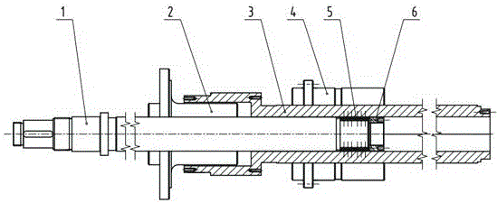
[0031] Such as figure 1 As shown, the new multi-stage screw with rolling friction combination has a two-stage screw structure, the second-stage screw is set outside the first-level screw, and adopts the structure of stacked sets, and each screw is equipped with a nut. It includes a primary lead screw (1), a primary nut (2), a secondary lead screw (3), a secondary nut (4), a polygonal rolling friction pair (5), and a lock nut (6). The polygonal rolling friction pair (5) adopts a regular hexagonal structure. Among them, the first and second screw screws can be screw screws of various specifications and types, such as trapezoidal screw screws, ball screw screws, and planetary roller screw screws.

[0032] The polygonal rolling friction pair (5) is installed on the rear end of the primary screw (1) and axially fixed by the lock nut (6). The rear end of the primary screw (1) adopts a regular hexagonal structure, and the secondary screw ( 3) The inner hole is also a regular hexago...

Embodiment 2

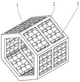
[0037] Such as image 3 As shown in , the new rolling friction combined multi-stage lead screw is a three-stage lead screw structure, the three-stage lead screw is stacked, and each lead screw is matched with a nut, including the first-stage lead screw (1) and the first-stage nut (2) , secondary screw (3), secondary nut (4), tertiary screw (5), tertiary nut (6), first polygonal rolling friction pair (7), first lock nut (8 ), the second polygonal rolling friction pair (9), and the second lock nut (10). The two polygonal rolling friction pairs are fixed on the rear end of the front-stage screw, and the fixing method adopts the inner and outer polygonal fit, and is axially positioned by the lock nut.

[0038] The primary nut (2) is installed on the primary screw (1), the inner ring of the first polygonal rolling friction pair (7) is installed on one end of the primary screw (1), and the first locking nut (8) For axial fixing, the outer ring is connected with the polygonal inner...

Embodiment 3

[0043] On the basis of the first embodiment, the roller structure in the polygonal rolling friction pair structure is replaced by a ball structure, and two polygonal rolling friction pairs are arranged between the primary screw and the secondary screw. The two polygonal rolling friction pairs are fitted and fixed on the primary lead screw respectively, and the two polygonal rolling friction pairs are matched with the inner hole of the secondary lead screw at the same time. Both the polygonal rolling friction pair and the inner hole of the secondary screw adopt a pentagonal structure. Two polygonal rolling friction pairs are fixed on the primary lead screw in the form of internal and external splines.

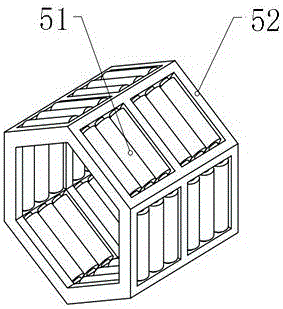
[0044] Figure 2B Middle: The polygonal ball friction pair consists of a polygonal protective frame (3), an inner cage (2), and balls (1). The balls (1) are spaced and evenly arranged by the inner cage (2), and the inner cage (2) is installed on the polygonal cage (3), and the...


PUM


Abstract

The invention provides a novel rolling friction combined multilevel screw rod. The novel rolling friction combined multilevel screw rod is simple and compact in structure, high in reliability and efficiency, not prone to being abraded and capable of achieving high-speed operating and precisely transmitting torque. The novel rolling friction combined multilevel screw rod comprises n levels of screw rod nut pairs; screw rod bodies of the two adjacent levels of screw rod nut pairs are connected through at least one polygonal rolling friction pair; and each polygonal rolling friction pair is fixedly installed on the corresponding front level of screw rod body and configured in a polygonal inner hole of the corresponding next level of screw rod body, so that multilevel screw rod linkage is achieved. According to the novel rolling friction combined multilevel screw rod, the structure is compact, assembling is convenient and reliable, and the torque of the front level of screw rod body can be reliably and precisely transmitted to the next level of screw rod body, so that the two levels of screw rod bodies can do corresponding synchronous rotating movement; and the multilevel screw rod has the characteristics of being stable and reliable in rotating, high in efficiency, sensitive in response, free of retardation and the like, and a very good screw rod synchronous effect can be achieved.

Description

Technical field: [0001] The invention relates to a novel rolling friction combined multi-stage lead screw, which belongs to the technical field of mechanical transmission. It can be widely used in electric vertical and vertical devices, electric lifting and extension, CNC machine tools, control execution systems, positioning systems, plastic machinery, military industry, high-load linear motion systems, measuring equipment, low-speed rotary motion, etc., to convert rotary motion into In the case of linear motion with long strokes. Background technique: [0002] At present, the common structural form of torque transmission between multi-stage screw pairs is: between the primary screw and the secondary screw, a set of double keys on opposite sides or two sets of double keys on opposite sides are used to transmit torque, and the flat keys are in the keyway. Sliding friction, this method of torque transmission will cause the flat key to fail in practical applications, and the...

Claims


Application Information

Patent Timeline
Patent Type & Authority Applications(China)
IPC IPC(8): F16H25/22
CPCF16H25/2204
Inventor 王建波
Owner 王建波
Learn More