Composite light guide plate

A light guide plate and surface layer technology, which is applied in the field of light guide plates, can solve the problems affecting the durability and light guide performance of the light guide plate, cannot meet the needs of laser engraving outlets, and poor water absorption performance of the plate, so as to improve the utilization rate of light sources and laser processing performance Good, low coefficient of water expansion

Pending Publication Date: 2016-12-14
DONGGUAN XINJU OPTRONICS INC
View PDF10 Cites 1 Cited by
  • Summary
  • Abstract
  • Description
  • Claims
  • Application Information

AI Technical Summary

Problems solved by technology

Therefore, in order to reduce costs, composite structures are mostly used at present, combining low-cost plates and high-cost plates, while reducing costs, its light-guiding performance can still meet the use of TVs and flat-panel displays.
However, there is still no public technical solution to how low-cost composite plates are suitable for laser engraving dot processing.
[0004] Secondly, large-sized TVs and flat-panel displays will be deformed due to poor water absorption of the board, which will affect the durability and light guiding performance of the light guide plate.
Chinese invention patent CN 104122618 A discloses a composite light guide plate, in which the middle layer is made of PC boards and both sides are made of PS boards. After compounding, the deformation problem of the boards can be solved to a certain extent. It cannot meet the requirements of laser engraving outlets, so there are still many technical problems that need to be improved

Method used


Image

  • Composite light guide plate

Examples


Embodiment 1

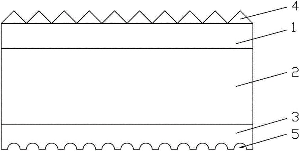
[0022] A composite light guide plate, comprising MS surface layer (1), PS base layer (2), MS bottom layer (3) from top to bottom, said MS surface layer (1), PS base layer (2), MS bottom layer (3) Composite connection is adopted in a co-extrusion film compound method, the MS bottom layer (3) is provided with a light guide dot layer (5) carved by laser, and the MS surface layer (1) is provided with a mold The thermoformed prism array surface layer (4).

[0023] The thickness of the PS matrix layer (2) is 60% of the total thickness of the composite light guide plate.

[0024] The prisms in the prism arrangement surface layer (4) are formed into V-shaped polygonal rhomboids, the distance between the peaks of two adjacent V-shaped polygonal rhomboids is 30um, and the height range of the prisms is 15um.

[0025] In the specific production, the prepared MS plate raw materials and PS plate raw materials are selected and put into two screw extruders respectively. After the screw is me...

Embodiment 2

[0029] A composite light guide plate, comprising MS surface layer (1), PS base layer (2), MS bottom layer (3) from top to bottom, said MS surface layer (1), PS base layer (2), MS bottom layer (3) Composite connection is adopted in a co-extrusion film compound method, the MS bottom layer (3) is provided with a light guide dot layer (5) carved by laser, and the MS surface layer (1) is provided with a mold The thermoformed prism array surface layer (4).

[0030] The thickness of the PS matrix layer (2) is 96% of the total thickness of the composite light guide plate.

[0031] The prisms in the prism arrangement surface layer (4) are formed into V-shaped polygonal rhomboids, the distance between the peaks of two adjacent V-shaped polygonal rhomboids is 500um, and the height range of the prisms is 150um.

[0032] In the specific production, the prepared MS board material and PS board material are selected and put into two screw extruders respectively. After the screw is melted, it...

Embodiment 3

[0036] A composite light guide plate, comprising a MS surface layer (1), a PS base layer (2), and an MS bottom layer (3), the MS surface layer (1), PS base layer (2), and MS bottom layer (3) adopt a common Composite connection in extruded film, the MS bottom layer (3) is provided with a light guide dot layer (5) carved by laser, and the MS surface layer (1) is provided with diamonds formed by hot pressing of molds. Mirror arrangement finish (4).

[0037] The thickness of the PS matrix layer (2) is 45% of the total thickness of the composite light guide plate.

[0038] The prisms in the prism arrangement surface layer (4) are formed into V-shaped polygonal rhomboids, the distance between two adjacent V-shaped polygonal rhomboids is 350um, and the height range of the prisms is 100um.

[0039] In the specific production, the prepared MS board material and PS board material are selected and put into two screw extruders respectively. After the screw is melted, it enters the co-ext...


PUM


Abstract

The invention discloses a composite light guide plate, which is characterized by comprising an MS surface layer (1), a PS matrix layer (2) and an MS bottom layer (3) in sequence from top to bottom, wherein the surface layer (1), the PS matrix layer (2) and the MS bottom layer (3) are compositely connected in a coextruded intra-membrane composite mode, a light guide lattice point layer (5) engaged by laser is arranged on the MS bottom layer (3), and a prism arrangement surface layer (4) formed by mold hot pressing is arranged on the MS surface layer (1). The composite light guide plate has the advantages that the cost of the composite light guide plate is lower than that of a light guide plate made of PMMA, MS or the like, so that the cost can be greatly reduced; the laser processing performance is good, and laser engraved pits are unlikely to carbonize, crack and zigzag; the water absorbing expansion performance is poor, the problems of dark fringes, black spots and the like caused by water absorbing deformation of the light guide plate are avoided, and the problems of ink drop and the like in use are simultaneously avoided.

Description

technical field [0001] The invention relates to the field of light guide plates, in particular to a composite light guide plate. Background technique [0002] With the continuous development of light guide plate technology, the dot processing technology of light guide plate is changing from screen printing to laser engraving. The light guide plate produced by laser engraving dot technology has uniform dot layout, more uniform light guide, and no dark lines and Pros of spotting. However, in actual production, when the laser engraving dot technology is used to process the light guide plate, due to the unavoidable damage to conventional plates such as PS plates due to the laser intensity, excessive carbonization of the laser points, cracks and jagged edges of the laser points will occur. , thus seriously affecting the light guiding performance of the light guide plate. [0003] In addition, depending on the way of use, the materials used for the light guide plate are also dif...

Claims


Application Information

Patent Timeline
Patent Type & Authority Applications(China)
IPC IPC(8): G02B6/00
CPCG02B6/0015G02B6/004G02B6/0053G02B6/0065
Inventor 蔡文珍
Owner DONGGUAN XINJU OPTRONICS INC
Why Eureka
Try Eureka