
Triangular grid tooth segmentation method based on path planning

A triangular mesh and path planning technology, applied in image analysis, image data processing, instruments, etc., can solve problems such as interference of central tooth socket line, burr of skeleton line, and difficulty in obtaining segmentation results

Active Publication Date: 2016-12-14
福州海狸家口腔科技有限公司
View PDF8 Cites 35 Cited by
  • Summary
  • Abstract
  • Description
  • Claims
  • Application Information

AI Technical Summary

Problems solved by technology

[0003] Most of the current 3D tooth segmentation methods use graphic image processing technology to extract the tooth morphological features of the jaw model to separate individual individual teeth. However, due to the limited accuracy of 3D scanning, the boundary between teeth and gums on the triangular mesh jaw The lines and the boundary lines between adjacent teeth are usually fused together, and the tooth shapes are different, so it is difficult to obtain good segmentation results with traditional segmentation methods, especially when the patient has deformed teeth, this problem is particularly prominent
Wu et al. (K.Wu, L.Chen, J.Li, et al. Tooth segmentation on dental meshes using morphologic skeleton, Computers & Graphics. 2014, 38:199–211) first extracted the boundary lines of teeth and gums based on the skeleton line method, Then the boundary line between adjacent teeth is obtained by matching the corner points of the boundary line, but it is easily disturbed by the burr of the skeleton line and the central tooth socket line during the matching process
Zou et al. (B.Zou, S.Liu, S.Liao, et al. Interactive tooth partition of dental mesh base on tooth-targetharmonic field, Computers in Biology and Medicine, 2015, 56:132–144) proposed a method based on Harmonic field tooth segmentation method, but requires a lot of user interaction to set the constraint points of the tooth boundary

Method used


Image

  • Triangular grid tooth segmentation method based on path planning
  • Triangular grid tooth segmentation method based on path planning
  • Triangular grid tooth segmentation method based on path planning

Examples


Embodiment Construction

[0050] Embodiments of the present invention will be further described below with reference to the accompanying drawings:

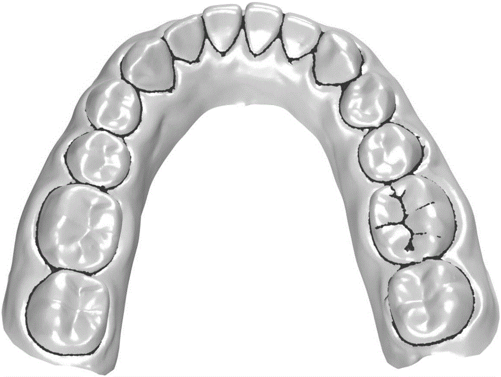
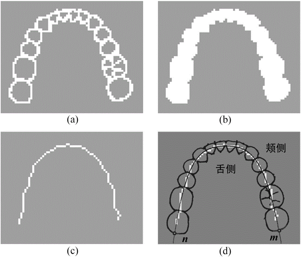
[0051] Such as figure 1 As shown, the present invention mainly includes six steps: 1. Select tooth anatomical feature points to determine the occlusal plane; 2. Use the curvature information of the dental model to extract the tooth feature area; 3. Project the feature area to fit the dental arch line; 4. Search for the gum line based on the quadratic path planning algorithm; 5. Segment the gum line and search for the suture line; 6. Combine the gum line and the suture line to form a tooth segmentation line, and segment the teeth based on the region growing algorithm.

[0052] Step 1. Determine the occlusal plane: interactively select tooth anatomical feature points on the three-dimensional dental model: the mesiolingual point of the first molar, the incisal point of the central incisor, and then use the principal component analysis method to fit these poin...


PUM


Abstract

The invention provides a triangular grid tooth segmentation method based on path planning. The method comprises the following steps that 1, tooth anatomical feature points are selected so as to determine the plane of occlusion; 2, tooth feature areas are extracted by using curvature information of a dental model; 3, projection of the feature areas is performed so as to perform fitting of dental arches; 4, gum lines are searched based on a secondary path planning algorithm; 5, the gum lines are segmented and tooth slit lines are searched; and 6, the gum lines and the tooth slit lines are combined to form tooth segmentation lines and the teeth are segmented based on a region growing algorithm. The triangular grid tooth segmentation method based on path planning has less artificial intervention and parameter adjustment and is suitable for various dental models of the problems of the distorted teeth and the crowded dental arches so as to have important significance in enhancing the effect of orthodontic treatment.

Description

technical field [0001] The invention belongs to the field of computer graphics, and relates to a triangular mesh tooth segmentation method based on path planning for automatically segmenting all teeth from a triangular mesh dental jaw model. Background technique [0002] With the continuous development of three-dimensional measurement and computer graphics technology, computer-aided diagnosis and restoration have been widely used in orthodontics. In the orthodontic system, in order to simulate the movement of the teeth and gums and formulate a treatment plan, it is necessary to first segment each tooth from the digital 3D jaw model. Therefore, the accuracy and integrity of the segmentation are directly related to the final treatment effect and design cost. [0003] Most of the current 3D tooth segmentation methods use graphic image processing technology to extract the tooth morphological features of the jaw model to separate individual individual teeth. However, due to the ...

Claims


Application Information

Patent Timeline
IPC IPC(8): G06T7/00
CPCG06T7/0012G06T2207/30036
Inventor 吴婷张礼兵
Owner 福州海狸家口腔科技有限公司
Learn More