Antenna Arrays and Antennas
An antenna array and antenna technology, applied to antenna arrays, antennas, electrical components, etc., to achieve miniaturization design, increase gain, and increase the effect of front-to-back ratio indicators
- Summary
- Abstract
- Description
- Claims
- Application Information
AI Technical Summary
Problems solved by technology
Method used
Image
Examples
Embodiment 1
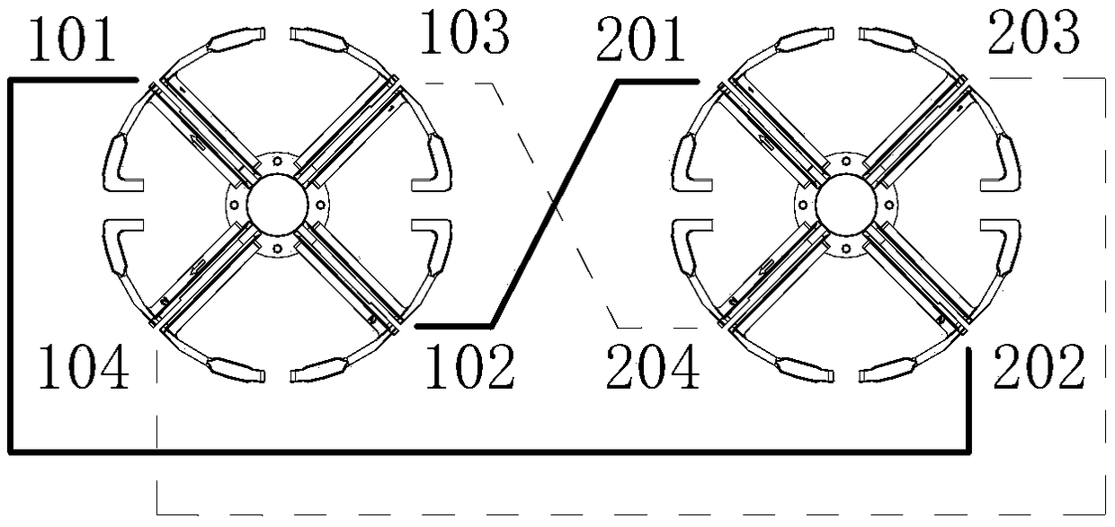
[0030] In this embodiment, the antenna array includes at least one first radiating unit (unnumbered, the same below) and at least one second radiating unit (unnumbered, the same below), and the first and second radiating units are double The polar oscillators each include two pairs of dipoles with orthogonal polarizations. In the antenna array, one first radiating unit and one second radiating unit are arranged side by side on the antenna reflector in a one-to-one correspondence, so as to construct two rows of antennas on the left and right.
[0031] like figure 1 shown in figure 1 In , the solid line represents the feeder of the antennas in the left column, and the dotted line represents the feeder of the antennas in the right column. Taking a first radiating unit and a second radiating unit arranged in parallel as an example, the first radiating unit (that is, a dual-polarized vibrator on the left) includes two pairs of dipoles 101, 102, 103, 104 with orthogonal polarizati...
Embodiment 2
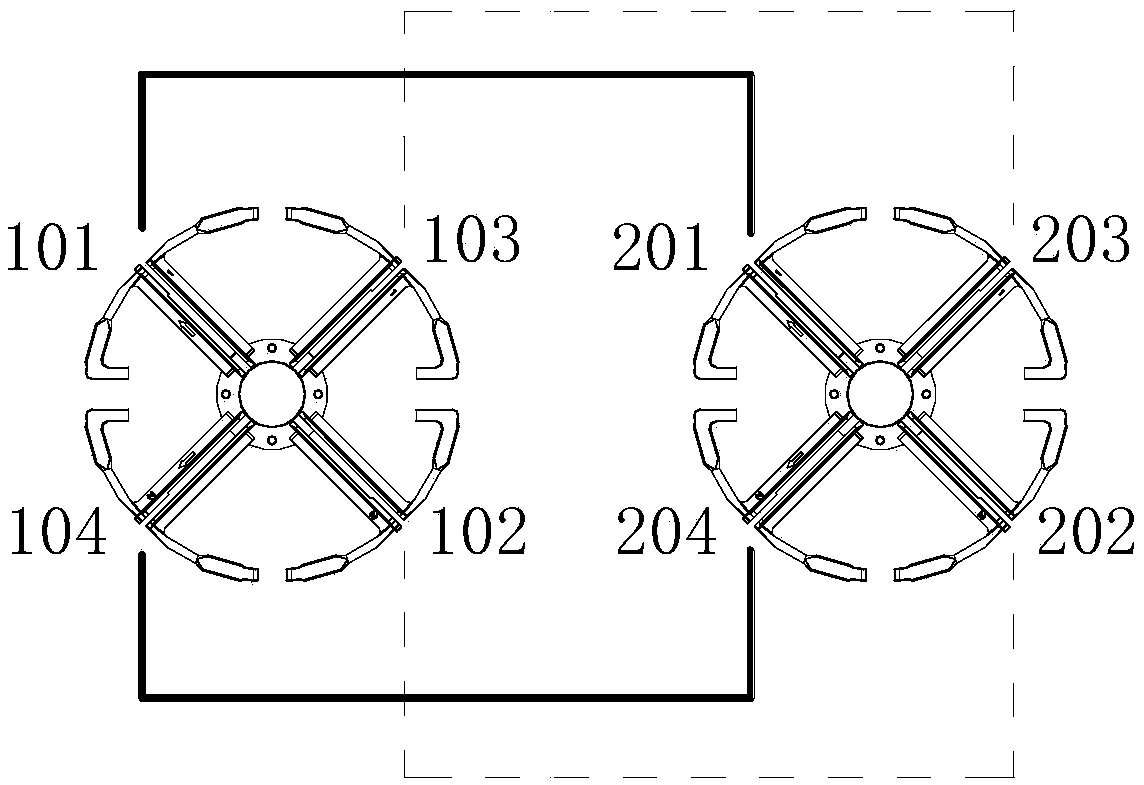
[0038] The antenna array of this embodiment is similar to Embodiment 1, the difference lies in:
[0039] see figure 2 , in this embodiment, the dipole 101 and the dipole 201 are arranged in parallel as the positive polarization of the left column antenna. Similarly, dipole 104 and dipole 204 are connected in parallel as the negative polarization of the left antenna, and dipole 102 and dipole 202 are connected in parallel as the right polarization of the antenna. Dipole 103 and dipole The poles 203 are connected in parallel in an array as the negative polarization of the right column antenna.
Embodiment 3
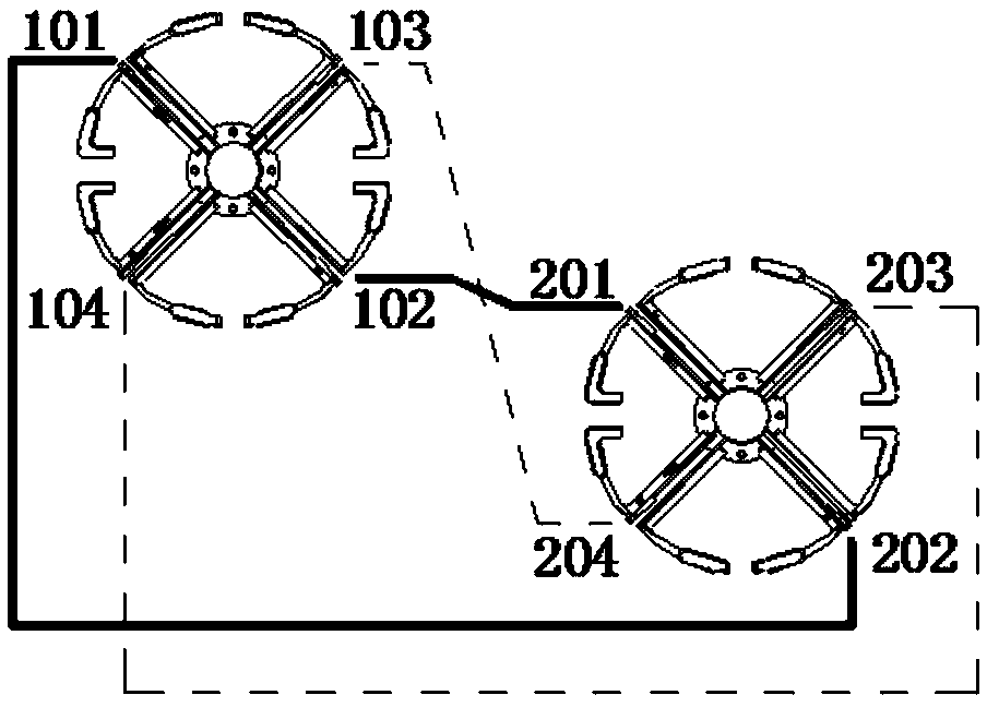
[0041] The antenna array of this embodiment is similar to Embodiment 1, the difference lies in:
[0042] see image 3 , in this embodiment, the first and second radiating elements of the left and right antenna arrays are vertically staggered, that is, the line connecting the centers of the two dual-polarized oscillators corresponding to the array is an oblique line.
PUM
 Abstract
Description
Claims
Application Information
 - R&D
- Intellectual Property
- Life Sciences
- Materials
- Tech Scout
- Unparalleled Data Quality
- Higher Quality Content
- 60% Fewer Hallucinations
Browse by: Latest US Patents, China's latest patents, Technical Efficacy Thesaurus, Application Domain, Technology Topic, Popular Technical Reports.
© 2025 PatSnap. All rights reserved.Legal|Privacy policy|Modern Slavery Act Transparency Statement|Sitemap|About US| Contact US: help@patsnap.com


