MOSFET/IGBT high-speed driving circuit based on linear optical coupling isolation
A drive circuit, linear optocoupler technology, applied in electrical components, electronic switches, pulse technology, etc., can solve problems such as abnormal output waveform, low operating frequency of MOSFET/IGBT drive circuit, and abnormal operation of power electronic systems
- Summary
- Abstract
- Description
- Claims
- Application Information
AI Technical Summary
Problems solved by technology
Method used
Image

Examples
Embodiment
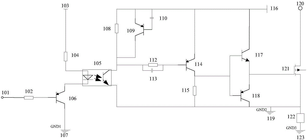
[0023] Such as figure 1As shown, a MOSFET / IGBT high-speed drive circuit based on linear optocoupler isolation, the control signal is input from the drive circuit control signal input terminal 101, when the control signal is at a high level, the first PNP transistor 106 is turned off, and the linear optocoupler No current flows through the LED in 105 , the collector and emitter of the linear optocoupler 105 are in a high-impedance state, the output signal is at high level, and the voltage of the first capacitor 110 is about zero. When the control signal changes from high level to low level, the first PNP transistor 106 is turned on, the light-emitting diode in the linear optocoupler 105 passes current, and the collector and emitter of the linear optocoupler 105 are in a low resistance state, and the output The signal voltage starts to drop, and the third resistor 108 provides current to the linear optocoupler 105 . Due to the clamping effect of the first capacitor 110 , the sec...
PUM
 Abstract
Description
Claims
Application Information
 - R&D
- Intellectual Property
- Life Sciences
- Materials
- Tech Scout
- Unparalleled Data Quality
- Higher Quality Content
- 60% Fewer Hallucinations
Browse by: Latest US Patents, China's latest patents, Technical Efficacy Thesaurus, Application Domain, Technology Topic, Popular Technical Reports.
© 2025 PatSnap. All rights reserved.Legal|Privacy policy|Modern Slavery Act Transparency Statement|Sitemap|About US| Contact US: help@patsnap.com