
an intervertebral fusion

An intervertebral cage and cage technology are applied in the field of intervertebral cages, which can solve problems such as cage displacement, and achieve the effects of simple installation structure, space saving, and speeding up the operation rate.

Active Publication Date: 2018-04-13
蒋毅
View PDF7 Cites 0 Cited by
  • Summary
  • Abstract
  • Description
  • Claims
  • Application Information

AI Technical Summary

Problems solved by technology

[0004] The purpose of the present invention is to provide an intervertebral fusion device to solve the technical problem of displacement of the fusion device before postoperative bone healing in the prior art

Method used


Image

  • an intervertebral fusion
  • an intervertebral fusion
  • an intervertebral fusion

Examples


Embodiment 1

[0034] The specific implementation of this embodiment is as follows:

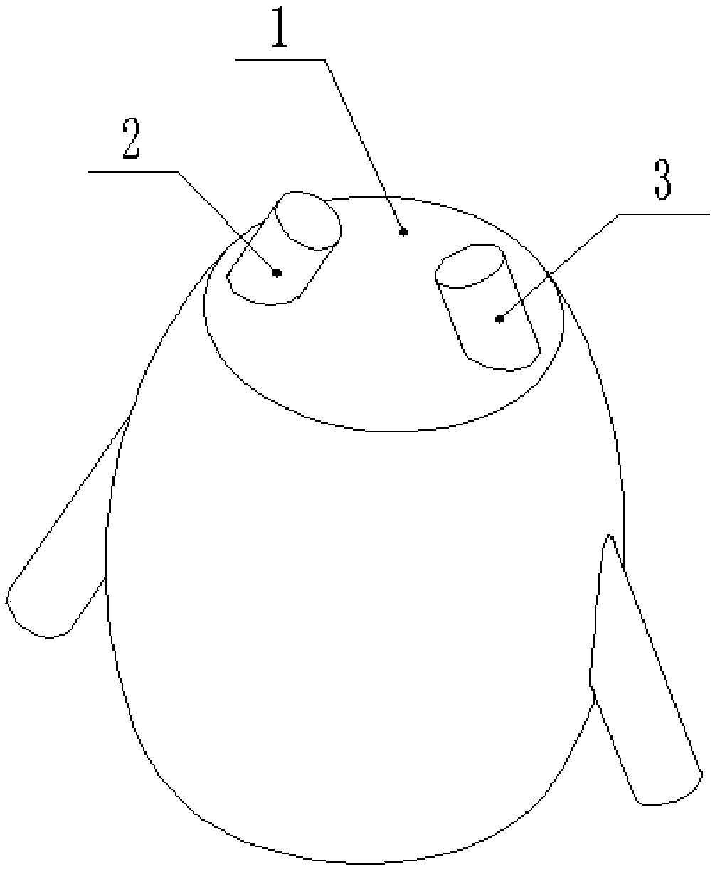
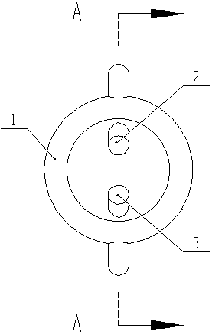
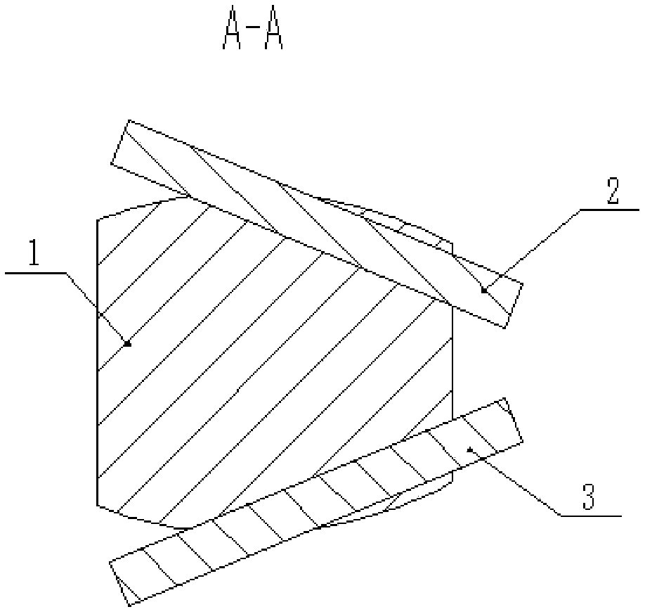
[0035] Such as Figure 1-7 As shown, a kind of intervertebral fusion device provided by this embodiment includes a fusion device body 1, the fusion device body 1 is a fusiform body, and the upper and lower end faces of the fusiform body are both planes; A plurality of locking positioning holes are provided in an obliquely downward direction; locking screws are also included, and the locking screws pass through the locking positioning holes to securely connect the fusion cage body 1 with the lumbar spine.

[0036] It should be noted that, compared with the existing fusion cages, the above-mentioned intervertebral fusion cage with self-locking function has a simple installation structure, is convenient to use, can speed up the operation speed, saves space, and makes the patient feel more comfortable. A locking positioning hole is opened on the cage body 1 to avoid the use of external cumbersome fixtures to f...

Embodiment 2

[0053] The intervertebral fusion device described in this embodiment not only includes all the above-mentioned technical features, but also includes the following technical solutions:

[0054] Preferably, in the locking positioning hole of this embodiment, a mounting platform is provided at a position 2 mm away from the upper end surface of the fusion cage body 1, and a small hole is provided on the mounting platform along the opening direction of the locking positioning hole.

[0055] It should be noted that since there are two locking positioning holes in the best embodiment, there are also two small holes.

[0056] Specifically, the aperture of the small hole is smaller than the aperture of the locking positioning hole, and the locking screw passes through the small hole to lock and fix the first vertebral body 4 and the second vertebral body 5 respectively.

[0057] It should be noted that the setting of the installation platform can make the end surface of the locking scr...


PUM


Abstract

The invention relates to the technical field of lumbar surgery tools, in particular to a lumbar interbody fusion device and aims at solving the technical problem that a fusion device existing in the prior art easily displaces before postoperative bone healing. The lumbar interbody fusion device comprises a fusion device body, wherein the fusion device body is a spindle-shaped body, the upper end face and the lower end face of the spindle-shaped body are planes, and multiple locking and positioning holes are formed in the upper end face of the fusion device body in the oblique downward direction. The lumbar interbody fusion device further comprises locking screws, wherein the locking screws penetrate through the locking and positioning holes and are used for fixing and connecting the fusion device body and the lumbar vertebra. The lumbar interbody fusion device is provided with a stabilizing structure, is simple in structure and convenient to use and can be prevented from displacing with respect to the vertebral bodies on two sides and avoid postoperative bleeding and other phenomena.

Description

technical field [0001] The invention relates to the technical field of lumbar spine surgery tools, in particular to an intervertebral fusion device. Background technique [0002] At present, with the frequent occurrence of spinal diseases in people, the treatment methods for the spine are becoming more and more targeted. The spine consists of one vertebral body, two pedicles, two lamina, two transverse processes, four articular processes and one The bone structure composed of spinous processes is divided into cervical vertebrae, thoracic vertebrae, lumbar vertebrae, sacral vertebrae, and coccygeal vertebrae. Lumbar spine disease can be caused by bad habits or by momentary inappropriate behavior. [0003] Lumbar fusion surgery is currently the main method for treating lumbar diseases. Lumbar fusion combined with lumbar fusion device implantation has the advantages of maintaining intervertebral space height, reducing nerve root pressure, and maintaining spinal stability in th...

Claims


Application Information

Patent Timeline
Patent Type & Authority Patents(China)
IPC IPC(8): A61F2/44
CPCA61F2/4455A61F2310/00005A61F2310/00023
Inventor 蒋毅
Owner 蒋毅
Learn More