

Glue dispensing method and device
A technology of dispensing and location information, applied in the field of communication, can solve problems such as deviation, achieve the effect of eliminating deviation, improving dispensing effect, and improving accuracy
- Summary
- Abstract
- Description
- Claims
- Application Information
AI Technical Summary
Problems solved by technology
Method used
Image

Examples
no. 1 example
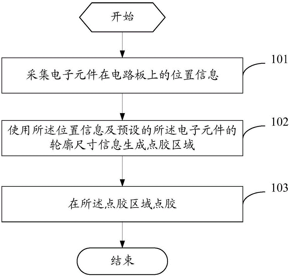
[0022] see figure 1 , figure 1 It is a flowchart of the dispensing method provided by the embodiment of the present invention, such as figure 1 shown, including the following steps:
[0023] Step 101, collecting position information of electronic components on a circuit board.
[0024] In this step, the position information of the electronic components welded on the circuit board is collected, wherein the position information is collected by an image sensor arranged on the glue dispenser. Image sensors can be classified into two categories, CCD (Charge Coupled Device, charge-coupled device) and CMOS (Complementary Metal-Oxide Semiconductor, metal oxide semiconductor element), according to different components. Since the CCD image sensor has the characteristics of high resolution, low noise, wide dynamic range, small size and light weight, the image sensor in this embodiment is preferably a CCD image sensor.
[0025] Step 102, using the position information and the preset o...
no. 2 example
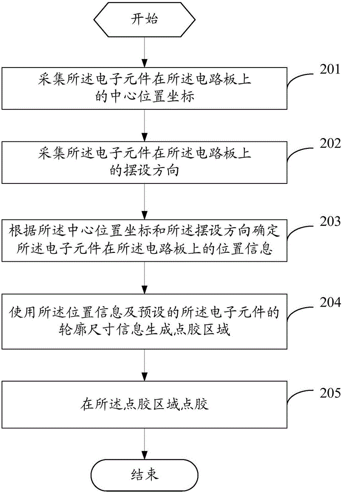
[0032] see figure 2 , figure 2 It is a flowchart of the dispensing method provided by the embodiment of the present invention, such as figure 2 shown, including the following steps:
[0033] Step 201, collect the coordinates of the center position of the electronic component on the circuit board.
[0034] In this step, the image information of the electronic components on the circuit board is collected by the CCD image sensor, and the image information of the electronic components on the circuit board is combined by using the preset proportional relationship between the basic size parameters of the electronic components and the basic size parameters of the circuit board Information can be used to obtain the coordinates of the center position of the electronic component on the circuit board.
[0035] Step 202, collect the arrangement direction of the electronic components on the circuit board.
[0036] In this step, the orientation of the electronic components on the cir...
no. 3 example
[0052] see Figure 4 , Figure 4 It is a structural diagram of the dispensing device provided by the implementation of the present invention, such as Figure 4 As shown, the dispensing device 400 includes an acquisition module 401, a generation module 402 and a dispensing module 403, wherein the acquisition module 401 is connected to the generation module 402, and the generation module 402 is also connected to the dispensing module 403:
[0053] The collection module 401 is used to collect the position information of the electronic components on the circuit board;
[0054] A generating module 402, configured to generate a dispensing area using the position information and the preset outline size information of the electronic component;
[0055] The glue dispensing module 403 is used for dispensing glue in the glue dispensing area.
[0056] optional, such as Figure 5 As shown, the collection module 401 block includes:
[0057] The first acquisition unit 4011 is configured...
PUM
 Abstract
Description
Claims
Application Information