Device for ground simulation of hanging and unfolding of solar wing plate

A ground simulation and hanging technology, which is applied in the field of solar wing deployment, can solve problems affecting the hanging and deployment of solar wing panels, bending of hanging rods, and affecting installation hinges, etc., to achieve increased rigidity, improved support, and simple structure compact effect

Active Publication Date: 2016-12-21
ZHEJIANG UNIV OF TECH
View PDF6 Cites 3 Cited by
  • Summary
  • Abstract
  • Description
  • Claims
  • Application Information

AI Technical Summary

Problems solved by technology

[0004] In the simulated deployment experiment of the solar wing on the ground, the deployment of the solar wing usually needs to be rotated 90 degrees around the rotation axis to complete the deployment action, and the length of the entire solar wing panel is usually about 3 meters, and the mass of a single solar wing panel is 10 Therefore, in the actual hanging process, the hanging rod needs to be rotated 90 degrees, the hanging point of the hanging rod will be subject to a large load, and a large bending moment will be generated at the hanging point, which is easy to causing bending of the hanging rod itself
[0005] Due to the high precision requirements in the vertical direction during the hanging process of the solar wing, the bending of the hanging rod will affect the vertical height of the solar wing, which may affect its installation hinges, etc. In the process of hanging the solar panel by the hanging rod, we must ensure the rigidity of the hanging rod, and at the same time ensure that it is in a horizontal state, otherwise a lateral force will be generated when the hanging rod rotates, which will seriously affect the hanging of the solar wing. and unfolding

Method used


Image

  • Device for ground simulation of hanging and unfolding of solar wing plate
  • Device for ground simulation of hanging and unfolding of solar wing plate

Examples


Embodiment Construction

[0015] The present invention will be further described below in conjunction with accompanying drawing:

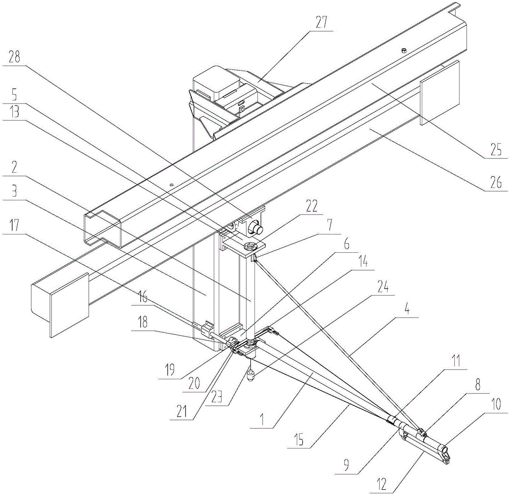
[0016] Such as Figure 1~2 As shown, a ground simulation hanging and deploying device for a solar wing panel comprises a horizontally arranged hanging rod 1, a vertically arranged support rod 2, a pull rod 4, an upper horizontal support 5, a lower horizontal support 6, a vertically fixed Beam 3, fixed beam limit frame 27, fixed beam movable frame 28, first tie bar seat 7, second tie bar seat 8, first short slide rail seat 9, second short slide rail seat 10, rocker arm frame stabilization sleeve 11 And short slide rail 12, described suspension rod 1 and support rod 2 are all hollow tubular, and one end of suspension rod 1 is fixed on the support rod 2 and can rotate with support rod 2 rotations, and the upper end horizontal support 5 and the lower end The horizontal supports 6 are all fixed on the vertical fixed beam 3, the upper horizontal support 5 and the lower horizonta...


PUM


Abstract

The invention discloses a device for ground simulation of hanging and unfolding of a solar wing plate. The device comprises a horizontal hanging rod, a vertical supporting rod, a pull rod, an upper-end horizontal supporting seat, a lower-end horizontal supporting seat, a vertical fixed beam, a fixed beam limiting frame, a fixed beam moving frame, a first pull rod seat, a second pull rod seat, a first short sliding rail seat, a second short sliding rail seat, a rocker frame stabilizing sleeve and a short sliding rail. With the device, all that is required for guaranteeing of the vertical state of the supporting rod and the horizontal state of the hanging rod is to guarantee the absolute horizontal state of the horizontal supporting seats, whether the hanging rod is horizontal cannot be measured directly, and whether the supporting rod in the vertical state is absolutely vertical cannot be measured, so that the horizontal state of the hanging rod can be guaranteed by directly measuring whether the horizontal supporting seats are horizontal by a horizontal gauge; when the hanging rod is detected to be not in the horizontal state, the hanging rod is adjusted horizontally by adjusting the vertical fixed beam, and whether the hanging rod is adjusted to be horizontal can be judged accurately through a laser emitter in the adjusting process.

Description

technical field [0001] The present invention relates to the technical field of solar wing deployment, and more specifically, relates to a ground simulation suspension and deployment device for a solar wing panel. Background technique [0002] The solar wing is the energy source of the satellite. The solar panel is a device that collects solar energy. It is usually used to supply energy for satellites and spacecraft, and can also be used to install on the top of environmentally friendly cars. The solar wing is the energy source of the satellite. When the satellite is launched, the solar wing is in a folded state. After the star rocket is separated, it is opened and the direction is constantly adjusted during the flight of the satellite, so that the solar cells are aligned with the sun to provide energy for the entire star. The solar wing monitoring camera can capture the deployment process and working status of the solar wing, and judge whether the solar wing is in normal c...

Claims


Application Information

Patent Timeline
Patent Type & Authority Applications(China)
IPC IPC(8): B64G7/00G01M99/00
CPCB64G7/00G01M99/00
Inventor 单晓杭陈雨晴陈浪
Owner ZHEJIANG UNIV OF TECH
Why Eureka
Try Eureka