Deflectors for conveyor discharge points

A technology of a diversion device and a conveyor, which is used in transportation and packaging, conveyors, conveyor objects, etc., can solve problems such as hindering material unloading and affecting the normal use of conveyors, so as to achieve low maintenance and avoid affecting production efficiency and structure. simple effect

Active Publication Date: 2018-12-04
CHINA SHENHUA ENERGY CO LTD +1
View PDF7 Cites 0 Cited by
  • Summary
  • Abstract
  • Description
  • Claims
  • Application Information

AI Technical Summary

Problems solved by technology

[0005] In view of this, the purpose of the present invention is to propose a diversion device for the unloading point of the conveyor to solve the problems of materials sticking and accumulating on the chute at the lower part of the conveyor, affecting the normal use of the conveyor, and hindering the unloading of materials.

Method used


Image

  • Deflectors for conveyor discharge points
  • Deflectors for conveyor discharge points
  • Deflectors for conveyor discharge points

Examples


Embodiment Construction

[0038] In order to make the object, technical solution and advantages of the present invention clearer, the present invention will be described in further detail below in conjunction with specific embodiments and with reference to the accompanying drawings. Wherein the same components are denoted by the same reference numerals. It should be noted that the words "front", "rear", "left", "right", "upper" and "lower" used in the following description refer to directions in the drawings. The terms "inner" and "outer" are used to refer to directions toward or away from, respectively, the geometric center of a particular component.

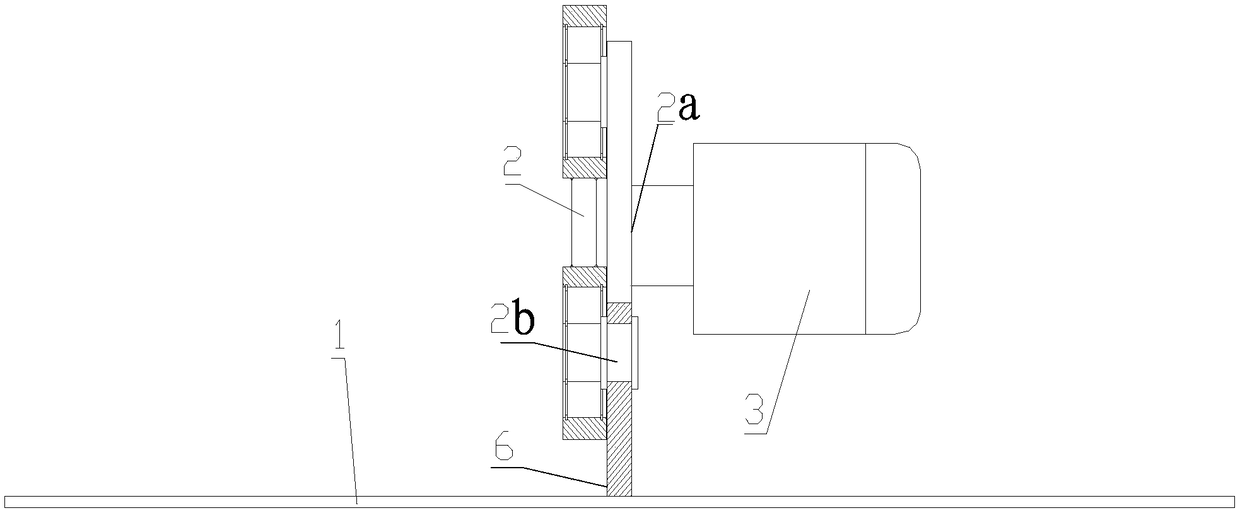
[0039] figure 1 It is a schematic diagram of the flow guiding device used in the unloading point of the conveyor used in the first embodiment of the present invention. Such as figure 1 As shown, the deflector used for the unloading point of the conveyor includes: a deflector 1 , a reciprocating mechanism 2 and a driving mechanism 3 .

[0040] Deflec...


PUM


Abstract

The invention discloses a flow-guiding device for a conveyor emptying point. The device comprises a flow-guiding plate, a reciprocating mechanism and a driving mechanism, wherein the reciprocating mechanism comprises a power input end and a power output end, the flow-guiding plate is fixed on the power output end, and the power output end is capable of driving the flow-guiding plate to reciprocate; the driving mechanism comprises an output end, the output end is connected with the power input end of the reciprocating mechanism, and the driving mechanism is used for driving the reciprocating mechanism to reciprocate; and the flow-guiding plate is obliquely arranged between a conveyor and a chute, the flow-guiding plate comprises a top and a bottom, the top of the flow-guiding plate is positioned below the emptying point of the conveyor, the bottom of the flow-guiding plate extends towards the oblique front lower side of the top, and the bottom of the flow-guiding plate extends to the upper side of the chute in front of the conveyor. The flow-guiding device for the conveyor emptying point, disclosed by the invention, is used for solving the problem that material unloading is blocked since materials are adhered and stacked on the chute below the conveyor.

Description

technical field [0001] The invention relates to the field of material conveying equipment, more specifically, to a flow guiding device for a discharge point of a conveyor arranged between a conveyor and a chute. Background technique [0002] Conveyors are used to transport materials and unload them to designated locations, and are widely used in various industries such as coal mines, power generation, and metallurgy. For example, when a power plant transports coal, because the unloading height is usually set at tens of meters, the conveyor is used in conjunction with the chute when unloading. The chute extends from the vicinity of the unloading point of the conveyor to the ground or other material points, and the coal is unloaded into the chute through the unloading point, and continues to move down on the chute. When unloading materials with high moisture content and high viscosity, such as raw coal with high moisture content, the raw coal may fall and stick to the chute u...

Claims


Application Information

Patent Timeline
Patent Type & Authority Patents(China)
IPC IPC(8): B65G47/44
CPCB65G47/44B65G2201/04
Inventor 李银广马元宝
Owner CHINA SHENHUA ENERGY CO LTD
Why Eureka
Try Eureka