A vibration wheel with self-lubricating structure

A self-lubricating, vibrating wheel technology, used in roads, buildings, road repairs, etc., can solve problems such as equipment failure, inability to release, and impact on the service life of the vibrating wheel, and achieve high lubrication and heat dissipation efficiency, sufficient lubrication, and sufficient heat dissipation. Effect

Active Publication Date: 2018-10-26
合肥永安绿地工程机械有限公司
View PDF10 Cites 0 Cited by
  • Summary
  • Abstract
  • Description
  • Claims
  • Application Information

AI Technical Summary

Problems solved by technology

Only relying on traditional heat dissipation and lubrication methods such as lubricating grease with low heat dissipation efficiency, a large amount of heat is generated and accumulated in the exciter cylinder and cannot be released, which is very easy to cause equipment failure, and the service life of the vibration wheel itself will inevitably be greatly affected. influences

Method used


Image

  • A vibration wheel with self-lubricating structure
  • A vibration wheel with self-lubricating structure
  • A vibration wheel with self-lubricating structure

Examples


Embodiment Construction

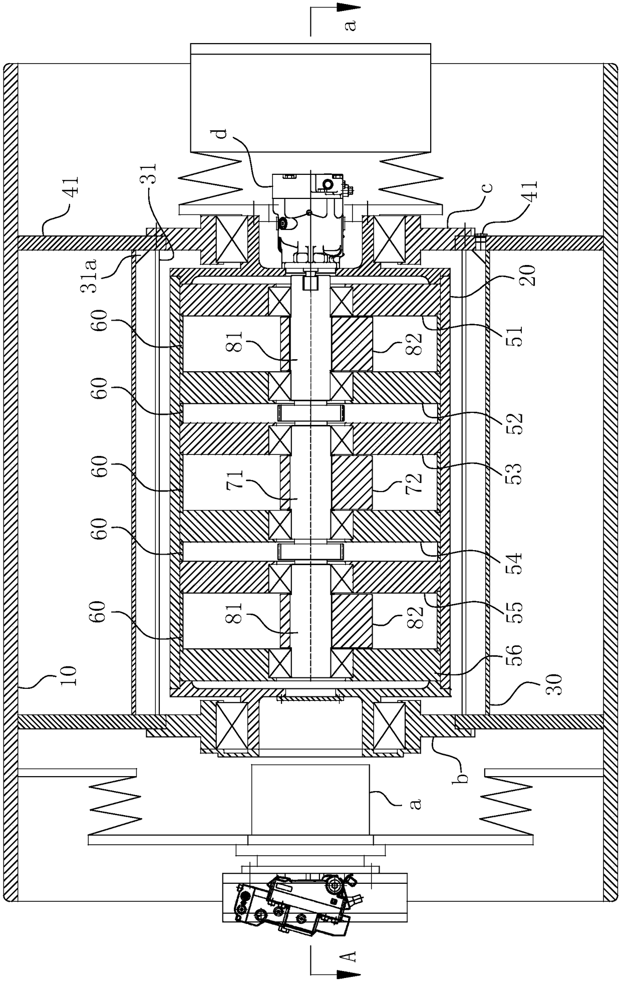
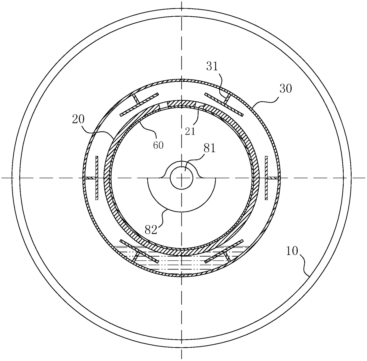
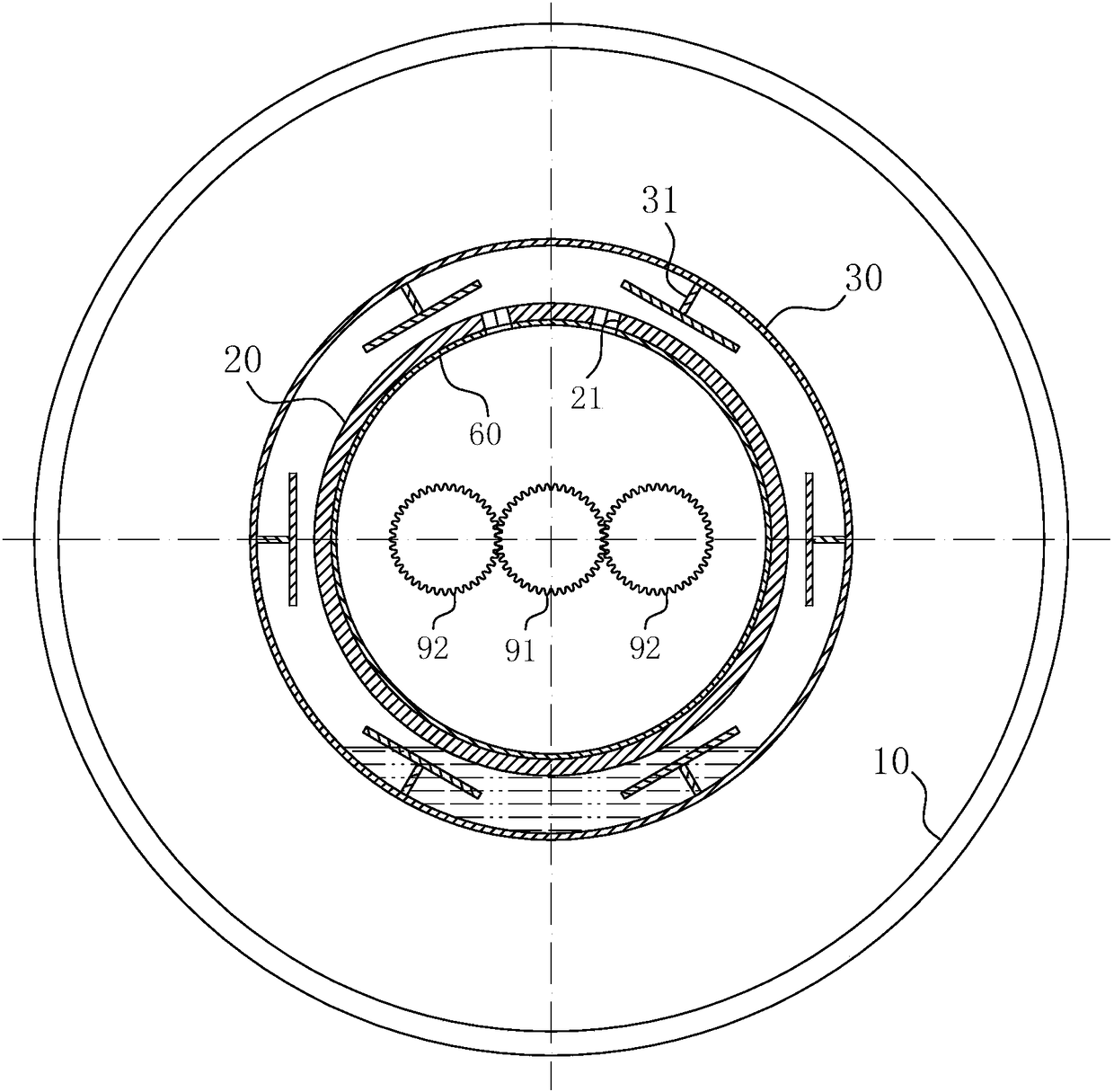
[0041] For ease of understanding, the attached Figure 1-8 Concrete structure and workflow of the present invention are described as follows:

[0042] Concrete structure of the present invention, can refer to Figure 1-6 As shown, it includes a steel wheel 10 as the outermost frame, an oil groove ring plate 30 is coaxially sleeved in the steel wheel 10 , and a vibrator cylinder 20 is coaxially sleeved in the oil groove ring plate 30 . Wherein, the vibrating wheel drive assembly a is arranged at the end of the steel wheel 10 in a suspended manner, and two ring-shaped webs 40 parallel to each other are radially arranged in the cylinder cavity of the steel wheel 10, and the webs 40 The oil groove ring plates 30 are connected to each other. The outer ring surface of the web 40 is fixedly connected to the cylinder cavity of the steel wheel 10, and the left support bearing b and the right support bearing c are clamped on the inner ring surface. An interference fixed fit is formed...


PUM


Abstract

The invention belongs to the field of road roller equipment, and specifically relates to a vibrating drum having a self-lubricating structure for use in a vibratory roller. The vibrating drum having a self-lubricating structure comprises a steel drum and an exciter barrel. A sleeve-shaped oil groove ring plate sleeves the exciter barrel. An oil inlet notch communicating a lubricating oil chamber and the cavity of the exciter barrel is formed in the outer wall of the exciter barrel. The oil inlet notch penetrates through the wall of the exciter barrel and communicates with a transmission gear and / or a bearing for supporting a set of eccentric blocks in the exciter barrel. T-form strip-shaped grooved plates are arranged on the inside annular surface of the oil groove ring plate, and the bottommost ends of the grooved plates are fixedly connected with the inside annular surface of the oil groove ring plate. The plate length direction of the grooved plates is parallel to the axis direction of the oil groove ring plate. More than two grooved plates are provided and evenly distributed at intervals in the circumferential direction of the oil groove ring plate. The vibrating drum having a self-lubricating structure allows for sufficient lubrication and heat dissipation of various kinematic members in the vibrating drum, and therefore, the use reliability and the service life of the vibrating drum are guaranteed eventually.

Description

technical field [0001] The invention belongs to the field of road roller equipment, and in particular relates to a vibration wheel with a self-lubricating structure used in a vibratory road roller. Background technique [0002] Vibratory rollers are machines that use their own gravity and vibration to compact various building and road construction materials; in highway construction, vibratory rollers are most suitable for compacting various non-cohesive soils, gravel, gravel mixtures and various widely used in asphalt concrete. The main structure of the current directional vibratory roller is usually composed of a steel wheel and an exciter barrel located in the cavity of the steel wheel; a vibration shaft is arranged in the cavity of the exciter barrel, and multiple shafts are arranged in sequence along the axial direction of the vibration shaft. The eccentric block groups independently have drive shafts and bearings, and finally drive each eccentric block group to rotate ...

Claims


Application Information

Patent Timeline
Patent Type & Authority Patents(China)
IPC IPC(8): E01C19/28
CPCE01C19/286
Inventor 宋皓黄方权崔文平
Owner 合肥永安绿地工程机械有限公司
Why Eureka
Try Eureka