
Hybrid opto-electronic energy lamp system

A photoelectric hybrid and lighting technology, which is applied in the direction of light sources, semiconductor devices of light-emitting elements, lighting devices, etc., can solve the problems of difficult to provide structure, low sunlight utilization rate, and high sunlight utilization rate, so as to reduce the use of LEDs and have industrial possibilities High efficiency, high efficiency of sunlight utilization

Inactive Publication Date: 2016-12-21
唐哲敏
View PDF5 Cites 0 Cited by
  • Summary
  • Abstract
  • Description
  • Claims
  • Application Information

AI Technical Summary

Problems solved by technology

In this case, if a lighting system with simple superposition of a group of photovoltaic energy sources as described above is used, then this situation may occur: the sunlight intensity is low, there are few places that need to be illuminated, and the total light energy collected is greater than the total light energy that needs to be illuminated. Light energy, but LED supplemental lighting is still required for each light fixture that is turned on
This is due to the low utilization of daylight due to the lack of scheduling of light energy
[0005] To sum up, it is difficult for the existing technology to provide a lighting product with compact structure, convenient use, stable brightness, and high utilization rate of sunlight.

Method used

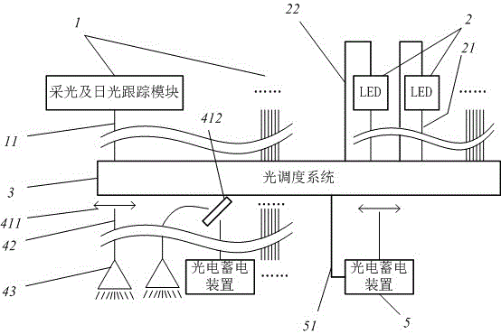

Image

  • Hybrid opto-electronic energy lamp system

Examples


Embodiment Construction

[0020] The following are specific embodiments of the present invention, and the solutions of the present invention will be further described with reference to the accompanying drawings, but the present invention is not limited to these embodiments.

[0021] Photoelectric hybrid energy lighting system consists of the following parts:

[0022] Several daylighting and daylight tracking modules 1, which track sunlight and input daylight into the daylighting optical fiber 11, the other end of the daylighting optical fiber 11 is connected to the light dispatching system 3; several LED modules 2, each LED module 2 has an LED power transmission line 22, and input the light emitted by the LED into the corresponding LED optical fiber 21, and the other end of the LED optical fiber 21 and the LED power line 22 are connected to the light dispatching system 3; the light dispatching system 3 controls the startup of the LED module 2 through the LED power line 22 and close; the light dispatchi...


PUM


Abstract

The invention relates to the field of lighting equipment, in particular to a hybrid opto-electronic energy lamp system which is small and exquisite in structure, convenient to use, stable in brightness and high in sunlight utilization ratio. The hybrid opto-electronic energy lamp system is composed of a plurality of daylighting and sunlight tracking modules, a plurality of LED modules and a light dispatching system. The light dispatching system makes the tail ends of a plurality of lighting optical fibers and the tail ends of a plurality of LED optical fibers align one faces of a plurality of condensing lenses or laterally face one faces of a plurality of semi-permeable mirrors. The other face of each condensing lens directly faces one terminal optical fiber. Each face of each semi-permeable mirror laterally faces one terminal optical fiber. One of the terminal optical fibers is connected with an opto-electronic storage device, and the remaining terminal optical fibers are connected with lamps correspondingly. The opto-electronic storage device supplies electric energy to the light dispatching system directly through an electric storage wire.

Description

technical field [0001] The invention relates to the field of lighting equipment, and more specifically, to a photoelectric hybrid energy lamp system with compact structure, convenient use, stable brightness and high sunlight utilization rate. Background technique [0002] As a new energy source, solar energy has the advantages of being inexhaustible, green and pollution-free. With the development of fiber optic technology, fiber optic lighting systems that directly use sunlight for lighting have developed rapidly. Its main applications include warehouses, underground parking lots, etc. When providing lighting, the safety problems of traditional circuit lighting are avoided. [0003] The biggest disadvantage of the daylight fiber optic lighting system is the instability of sunlight caused by the weather itself. Therefore, simply relying directly on sunlight for lighting will lead to unstable brightness of the lamps. In the prior art, when improving the brightness stability...

Claims


Application Information

Patent Timeline
Patent Type & Authority Applications(China)
IPC IPC(8): F21S19/00F21Y115/10
CPCF21S19/005
Inventor 唐哲敏
Owner 唐哲敏
Learn More