
High-frequency current sensor

A high-frequency current and sensor technology, used in instruments, measuring electricity, testing circuits, etc., can solve the problems of insufficient sensitivity, high sensitivity, narrow frequency band, etc., and achieve the effect of improving sensitivity, eliminating interference, and improving anti-interference ability.

Pending Publication Date: 2016-12-21
北京兴泰学成仪器有限公司
View PDF10 Cites 6 Cited by
  • Summary
  • Abstract
  • Description
  • Claims
  • Application Information

AI Technical Summary

Problems solved by technology

However, the existing high-frequency current sensors have defects in the design of wide frequency bands and insufficient sensitivity or high sensitivity and narrow frequency bands, or due to electromagnetic shielding defects in design, there are still certain problems in practical applications

Method used


Image

  • High-frequency current sensor
  • High-frequency current sensor
  • High-frequency current sensor

Examples


Embodiment Construction

[0022] In order to make the object, technical solution and advantages of the present invention clearer, the present invention will be described in further detail below in conjunction with specific embodiments and with reference to the accompanying drawings.

[0023] It should be noted that all expressions using "first" and "second" in the embodiments of the invention are used to distinguish two entities with the same name but different parameters or parameters that are not the same. It can be seen that "first" and "second" are only For the convenience of expression, it should not be understood as a limitation on the embodiments of the invention, and the following embodiments will not describe them one by one.

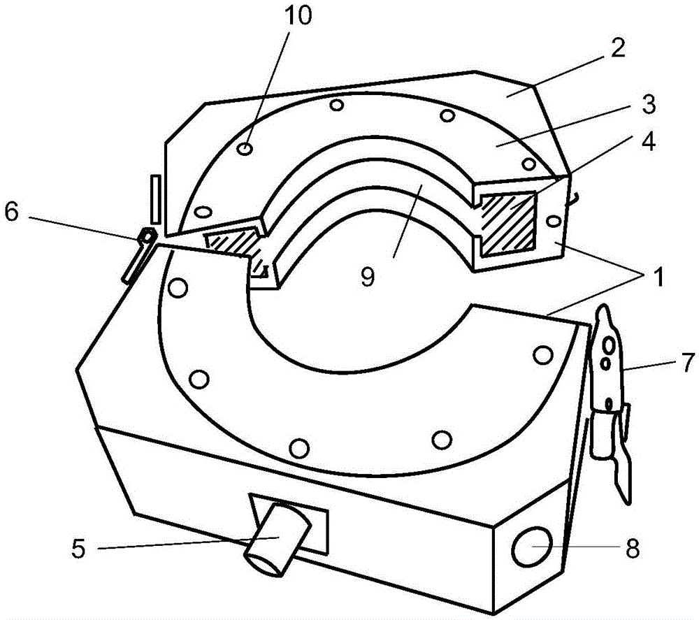
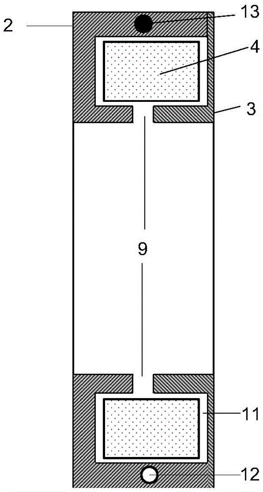
[0024] see figure 1 and figure 2 , are respectively a structural schematic diagram and a half-section left view of the high-frequency current sensor of the embodiment of the present invention. As an embodiment of the present invention, the high-frequency current sens...


PUM


Abstract

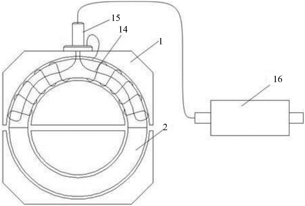
The invention discloses a high-frequency current sensor. The high-frequency current sensor comprises two metal shielding housings which are split; a groove is arranged in the inner wall of each metal shielding housing. A semi-ring type magnetic core is embedded in each groove. A ring-type slit through which the magnetic force passes is arranged in each groove. A gap is left between each semi-ring type magnetic core and the corresponding groove and is filled with insulation materials. When two ends of one metal shielding housing are connected with two ends of the other one metal shielding housing, the two semi-ring type magnetic cores in the metal shielding housings form a ring type magnetic core. Two segments of coils are wound on one of the semi-ring magnetic core in opposite winding directions. According to the invention, by introducing the difference amplifying principle into the high-frequency current sensor and taking full advantage of the characteristics of capability of effectively eliminating interference and amplifying original signals twice of a difference circuit, the anti-interference ability of the high-frequency current sensor is effectively improved and sensitivity of the sensor is greatly improved.

Description

technical field [0001] The invention relates to the technical field of partial discharge detection, in particular to a high-frequency current sensor used for partial discharge testing of cables and transformers. Background technique [0002] Partial discharge detection is an important test for testing the insulation status of high-voltage electrical equipment such as high-voltage switch GIS, transformers, generators, and power cables. In the prior art, in addition to directly measuring the partial discharge of high-voltage electrical equipment using the ultrasonic method and ultra-high frequency method, the internal partial discharge status of the high-voltage electrical equipment can also be detected by detecting the high-frequency current signal of the ground wire of the high-voltage electrical equipment. The high-frequency current method can not only detect the micro-signal of cable partial discharge caused by some tiny insulation defects, but also can monitor the insulat...

Claims


Application Information

Patent Timeline
Patent Type & Authority Applications(China)
IPC IPC(8): G01R31/12G01R31/14G01R1/04G01R1/16G01R1/18
CPCG01R1/04G01R1/16G01R1/18G01R31/1227G01R31/14
Inventor 章啸丁在松
Owner 北京兴泰学成仪器有限公司
Learn More