Electromagnetically driven unidimensional micro-mirror

A one-dimensional micromirror, electromagnetic drive technology, applied in optical components, optics, instruments, etc., can solve the problems of limiting the length of the driving coil, high driving voltage, small driving force, etc., to increase the magnetic induction intensity, realize large-angle deflection, The effect of enlarging the effective size

Inactive Publication Date: 2016-12-21
常州创微电子机械科技有限公司
View PDF8 Cites 8 Cited by
  • Summary
  • Abstract
  • Description
  • Claims
  • Application Information

AI Technical Summary

Problems solved by technology

[0003] 1. Electrostatic MEMS scanning micromirror: Although its driving method is simple and the power consumption is relatively small, its driving voltage is often high, and the driving force generated is small, which cannot provide the force required for the large-sized mirror torsion. , the current electrostatic MEMS micromirror has a small mirror surface and needs to work in a resonant state to achieve a large rotation angle
[0004] 2. Electrothermal MEMS scanning mirror: its drive is realized by integrating with the polysilicon heater in the metal oxide, and the deflection angle is relatively large under current drive, but due to the hysteresis effect of the thermal brake, the response speed of the micromirror is often relatively slow , not suitable for wide application in the field of laser scanning technology
[0006] 4. The current electromagnetic MEMS scanning micromirror places the driving coil and the reflecting surface on the same surface, which limits the effective size of the reflecting surface and the length of the driving coil, thereby reducing the driving torque and making the micromirror Unable to obtain large deflection angles

Method used


Image

  • Electromagnetically driven unidimensional micro-mirror
  • Electromagnetically driven unidimensional micro-mirror
  • Electromagnetically driven unidimensional micro-mirror

Examples


Embodiment Construction

[0022] The following will clearly and completely describe the technical solutions in the embodiments of the present invention. Obviously, the described embodiments are only some of the embodiments of the present invention, rather than all the embodiments. Based on the embodiments of the present invention, all other embodiments obtained by persons of ordinary skill in the art without making creative efforts belong to the protection scope of the present invention.

[0023] Embodiments of the invention include:

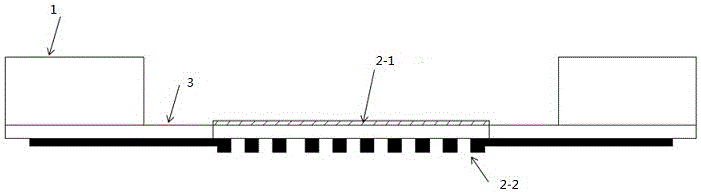
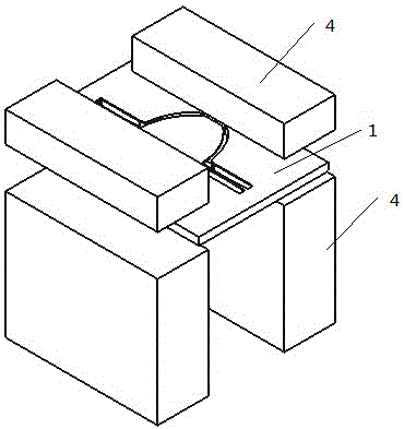
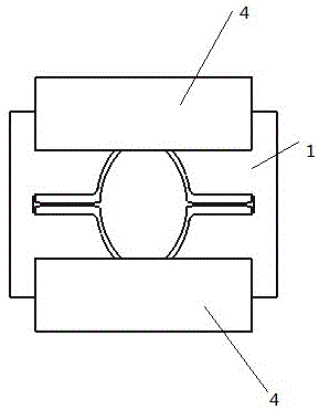
[0024] An electromagnetically driven one-dimensional micromirror, comprising: a base 1 and a mirror surface 2, the mirror surface 2 is erected on the base 1 by a torsion beam 3, and the torsion beam 3 is arranged at both ends of the mirror surface 2 and connected to the base 1 vertical set. The mirror surface 2 rotates around the torsion beam 3 at any angle. Such as figure 1 and figure 2 shown.

[0025] One side of the mirror 2 is a reflecting surface 2-1 for refle...


PUM


Abstract

The invention discloses an electromagnetically driven unidimensional micro-mirror. The micro-mirror is characterized in that the micro-mirror comprises a pedestal and a mirror face; the mirror face is erected on the pedestal through a torsion beam and rotates for any degree around the torsion beam; one face of the mirror face is used as a reflection face for reflection; and the other face of the mirror face is provided with an electromagnetic coil used for generating output torque. In this way, the whole structure of the micro-mirror is compact and two magnets are wrapped in the mirror face, so magnetic sensing intensity at the electromagnetic coil is increased and the output torque output by the driving coil is increased; the reflection face and the driving coil are placed in different planes, so compared with the manner in which the reflection mirror and the driving coil are placed in the same panel, the effective size of the mirror face can be extended; and meanwhile, by increasing the length of the coil, the output torque of the driving coil is increased, so large-angle deflection of a large-size micro-mirror is achieved.

Description

technical field [0001] The invention relates to the field of microelectronic machinery, in particular to an electromagnetically driven one-dimensional micromirror. Background technique [0002] Several existing MEMS micromirrors have the following deficiencies: [0003] 1. Electrostatic MEMS scanning micromirror: Although its driving method is simple and the power consumption is relatively small, its driving voltage is often high, and the driving force generated is small, which cannot provide the force required for the large-sized mirror torsion. , the current electrostatic MEMS micromirror has a small mirror surface and needs to work in a resonant state to achieve a larger rotation angle. [0004] 2. Electrothermal MEMS scanning mirror: its drive is realized by integrating with the polysilicon heater in the metal oxide, and the deflection angle is relatively large under current drive, but due to the hysteresis effect of the thermal brake, the response speed of the micromir...

Claims


Application Information

Patent Timeline
Patent Type & Authority Applications(China)
IPC IPC(8): G02B26/08
CPCG02B26/085
Inventor 沈文江余晖俊
Owner 常州创微电子机械科技有限公司
Why Eureka
Try Eureka