
Building construction informationized dynamic monitoring system

A technology for building construction and dynamic monitoring, applied in 3D modeling, other database browsing/visualization, image data processing, etc., can solve the problems of reduced accuracy in the monitoring process, data transmission failure, increased cost and time, etc., to achieve the elimination of security Information hidden dangers, avoiding security problems, maintaining normal operation effect

Inactive Publication Date: 2016-12-21
INNER MONGOLIA UNIV OF SCI & TECH
View PDF2 Cites 19 Cited by
  • Summary
  • Abstract
  • Description
  • Claims
  • Application Information

AI Technical Summary

Problems solved by technology

[0002] At present, people pay more and more attention to the safety of building construction. However, the previous monitoring is all artificial measurement and observation, and then evaluation and calculation. It is impossible to really evaluate the safety of building construction. At the same time, the detected data are all static. Yes, what will happen to the development of the deformation of the building, and the potential safety hazards that these deformation data will bring cannot be predicted and analyzed. Once the problem is discovered late, it will cause huge losses.
[0003] At the same time, the existing building construction monitoring data are transmitted through wired network or GPRS, 3G and other wireless methods, which greatly increases the cost and time required for erecting the entire system. At the same time, once the signal is poor, data transmission will fail, making monitoring Lack of continuity, which greatly reduces the accuracy of the entire monitoring process

Method used


Image

  • Building construction informationized dynamic monitoring system

Examples


Embodiment Construction

[0029] In order to make the objects and advantages of the present invention clearer, the present invention will be further described in detail below in conjunction with the examples. It should be understood that the specific embodiments described here are only used to explain the present invention, not to limit the present invention.

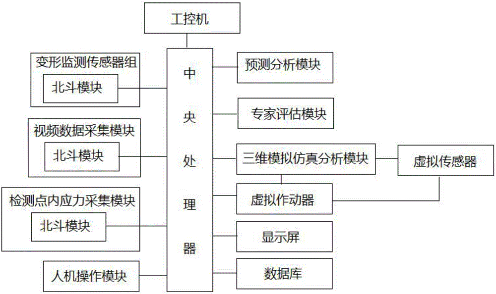
[0030] Such as figure 1 As shown, the embodiment of the present invention provides a dynamic monitoring system for building construction information, including

[0031] The deformation monitoring sensor group is installed at the real-time deformation monitoring point of the building for the collection of deformation data at the deformation monitoring point, and the collected data is sent to the central processor and the predictive analysis module through the Beidou module;

[0032] The video data acquisition module is used to collect high-resolution on-site deformation image data and building construction environment image data through digital ...


PUM


Abstract

The invention discloses a building construction informationized dynamic monitoring system. The building construction informationized dynamic monitoring system comprises an industrial control computer, a central controller, a digital camera, a deformation monitoring sensor group, a monitoring point internal stress acquisition module, a Beidou module, a prediction and analysis module and a three-dimensional analog simulation analysis module which are mutually connected, wherein the central controller controls the digital camera, the deformation monitoring sensor group and the monitoring point internal stress acquisition module to carry out data acquisition, the acquired data is sent to the prediction and analysis model and the central processor through the Beidou module, and analysis and prediction are carried out on building construction conditions through the prediction and analysis module and an expert evaluation model; a building construction three-dimensional model is built through the three-dimensional analog simulation analysis model, and carrying out three-dimensional analog simulation through a virtual actuator and a virtual sensor which are inserted into the three-dimensional model. The building construction informationized dynamic monitoring system can be applied to various construction environment fields, safety information hidden dangers in the construction process are eliminated, the construction fields are effectively detected and managed, and normal operations of a detection system at the construction fields are maintained.

Description

technical field [0001] The invention relates to a building construction monitoring system, in particular to a building construction information dynamic monitoring system. Background technique [0002] At present, people pay more and more attention to the safety of building construction, but the previous monitoring is all artificial measurement and observation, and then evaluates and calculates, so it is impossible to really evaluate the safety of building construction, and the detected data are all static Yes, what will happen to the development of the deformation of the building, and the potential safety hazards that these deformation data will bring cannot be predicted and analyzed. Once the problem is discovered late, it will cause huge losses. [0003] At the same time, the existing building construction monitoring data are transmitted through wired network or GPRS, 3G and other wireless methods, which greatly increases the cost and time required for erecting the entire ...

Claims


Application Information

Patent Timeline
IPC IPC(8): G06Q50/08G06F17/30G06T17/00
CPCG06Q50/08G06F16/904G06T17/00
Inventor 李建崔广芹姬晓璐
Owner INNER MONGOLIA UNIV OF SCI & TECH
Learn More