High-efficiency dual-frequency rectifying circuit

A rectifier circuit and voltage doubler rectifier circuit technology, which is applied to circuit devices, output power conversion devices, and AC power input to DC power output, etc. Rectification efficiency, improved output voltage, and clear design steps

Active Publication Date: 2016-12-21
SOUTH CHINA UNIV OF TECH
View PDF3 Cites 11 Cited by
  • Summary
  • Abstract
  • Description
  • Claims
  • Application Information

AI Technical Summary

Problems solved by technology

[0002] Most of the contemporary energy transmission is transmitted in the form of cables. These transmission methods not only consume a lot of manpower and material resources, but also in the environment of insufficient space, harsh environment and complex terrain, the use of cables will be greatly restricted.

Method used


Image

  • High-efficiency dual-frequency rectifying circuit
  • High-efficiency dual-frequency rectifying circuit
  • High-efficiency dual-frequency rectifying circuit

Examples


Embodiment

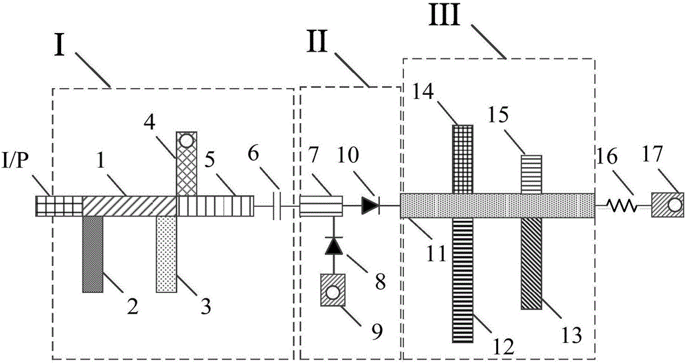
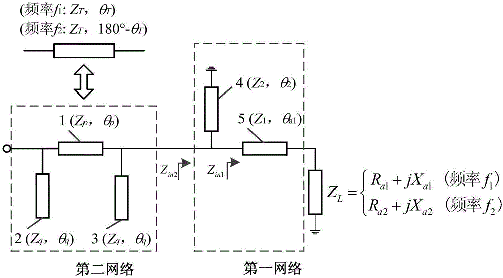
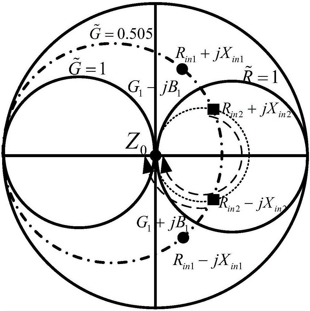
[0031] Such as figure 1 As shown, a high-efficiency dual-frequency rectifier circuit includes an upper microstrip structure, an intermediate dielectric substrate and a bottom metal floor, the upper microstrip structure is printed on the upper surface of the intermediate dielectric substrate, and the bottom metal floor is printed On the lower surface of the intermediate dielectric substrate, the upper microstrip structure is composed of a dual-frequency impedance matching network I, a voltage doubler rectification circuit structure II, a harmonic suppression network III and a load terminal connected in sequence. The design steps of the present invention are respectively designing the voltage doubler rectification circuit structure II, the harmonic suppression network III and the load end, and finally designing the dual-frequency impedance matching network I. The two operating frequencies in this embodiment are respectively the first operating frequency f 1 =915MHz, the second ...


PUM


Abstract

The invention discloses a high-efficiency dual-frequency rectifying circuit. The high-efficiency dual-frequency rectifying circuit comprises an upper layer microstrip structure, an intermediate dielectric substrate and a bottom layer metal floor, wherein the upper layer microstrip structure is printed on the upper surface of the intermediate dielectric substrate; the bottom layer metal floor is printed on the lower surface of the intermediate dielectric substrate; and the upper layer microstrip structure comprises a dual-frequency impedance matching network, a voltage doubling rectifying circuit structure, a harmonic suppression network and a load end which are connected in sequence. According to the high-efficiency dual-frequency rectifying circuit, due to the harmonic suppression network, the rectifying efficiency can be improved; due to the voltage doubling rectifying structure, the output voltage can be increased; and finally, by virtue of the regulation and control on the input impedance, the dual-frequency impedance matching network is designed, so that high rectifying efficiency of the disclosed rectifying circuit at two frequencies can be realized.

Description

technical field [0001] The invention relates to a microwave rectification circuit, in particular to a high-efficiency dual-frequency rectification circuit. Background technique [0002] Most of the contemporary energy transmission is transmitted in the form of cables. These transmission methods not only consume a lot of manpower and material resources, but also in the environment of insufficient space, harsh environment and complex terrain, the use of cables will be greatly restricted. Microwave Power Transmission is an energy transmission method that converts energy into microwaves and emits them from the transmitting end, and propagates them to the receiving end in free space. It breaks the traditional way of transmitting electric energy through cables and opens up A new way of energy transmission. [0003] Microwave energy transmission technology converts direct current into microwave energy through a microwave generator, and transmits it efficiently after being focused ...

Claims


Application Information

Patent Timeline
Patent Type & Authority Applications(China)
IPC IPC(8): H02J50/20H02M7/00H01Q1/22
CPCH01Q1/22H02M7/003
Inventor 章秀银刘建杜志侠
Owner SOUTH CHINA UNIV OF TECH
Why Eureka
Try Eureka