High-efficiency rectification circuit

A rectifier circuit, high-efficiency technology, applied in the direction of circuit devices, AC power input conversion to DC power output, electrical components, etc., can solve the problems of low circuit efficiency, limited frequency bandwidth, etc., to reduce loss, improve matching performance, improve The effect of rectification efficiency

Inactive Publication Date: 2016-02-24
SOUTH CHINA UNIV OF TECH
View PDF3 Cites 5 Cited by
  • Summary
  • Abstract
  • Description
  • Claims
  • Application Information

AI Technical Summary

Problems solved by technology

However, the circuits introduced in the above-mentioned related research articles generally have low efficiency and limited frequency bandwidth.

Method used


Image

  • High-efficiency rectification circuit
  • High-efficiency rectification circuit
  • High-efficiency rectification circuit

Examples


Embodiment

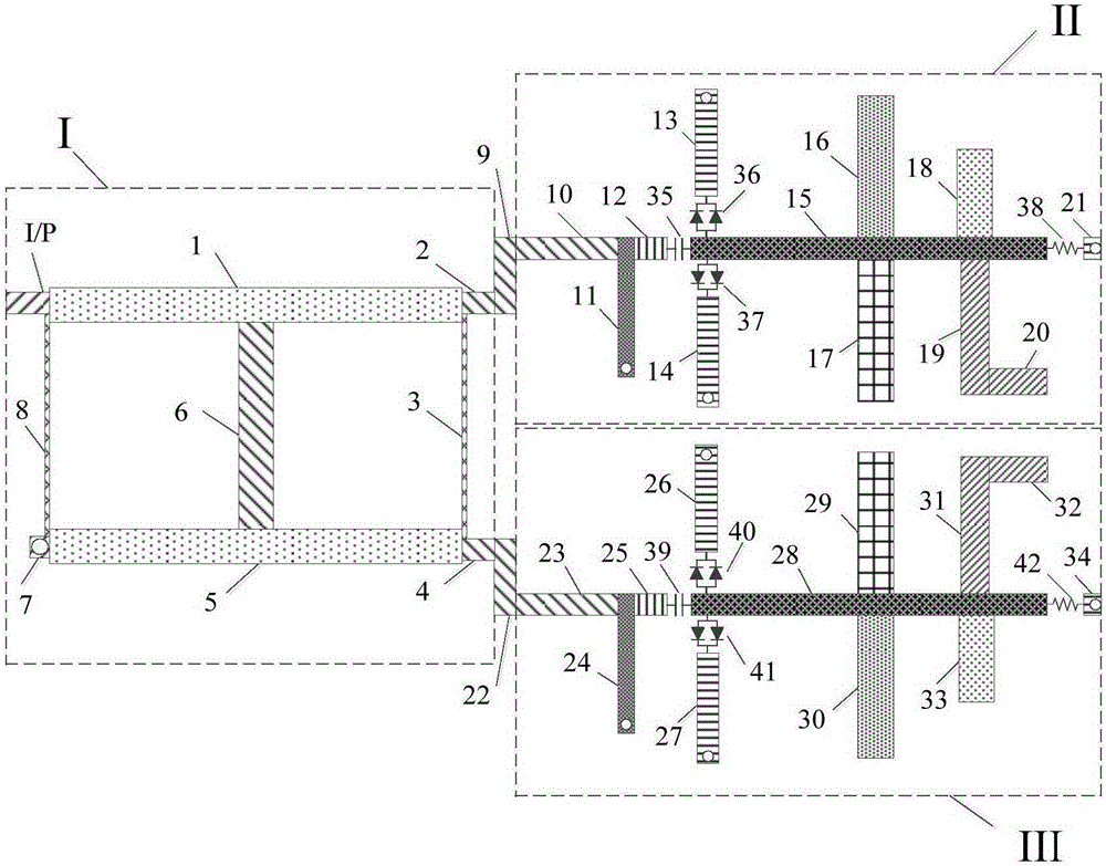
[0041] Such as figure 1 As shown, a high-efficiency rectifier circuit is characterized by comprising an upper microstrip structure, an intermediate dielectric substrate and a bottom metal floor, the upper microstrip structure is printed on the upper surface of the intermediate dielectric substrate, and the bottom metal floor is printed Manufactured on the lower surface of the intermediate dielectric substrate, the upper microstrip structure is composed of a two-section branch line coupler I, a first sub-rectifier circuit II, and a second sub-rectifier circuit III. The two-section branch line coupler passes through the The nine microstrip line 9 is connected to the first sub-rectifier circuit II, the two-section branch line coupler is connected to the second sub-rectifier circuit III through the twenty-second microstrip line 22, and the isolated ends of the two section line couplers pass Metalized vias are connected to the underlying metal floor. When the input power, frequency,...


PUM


Abstract

The invention discloses a high-efficiency rectification circuit. The high-efficiency rectification circuit comprises an upper layer microstrip structure, an intermediate medium substrate, and a bottom layer metal floor, the upper layer microstrip structure is printed on the upper surface of the intermediate medium substrate, and the bottom layer metal floor is printed on the lower surface of the intermediate medium substrate. The high-efficiency rectification circuit is characterized in that the upper layer microstrip structure is formed by a two-segment branch line coupler, a first sub-rectification circuit, and a second sub-rectification circuit, one isolation terminal of the two-segment branch line coupler is connected to the ground, and the two-segment branch line coupler is connected with the first sub-rectification circuit and the second sub-rectification circuit. According to the high-efficiency rectification circuit, the two-segment branch line coupler whose isolation terminal is connected to the ground is employed to re-inject a part of reflection waves generated by the two sub-rectification circuits due to impedance mismatch to the sub-rectification circuits for utilization, the rectification efficiency of the whole circuit is improved, better match between the whole rectification circuit and an antenna is realized, and the energy loss of the system is reduced.

Description

Technical field [0001] The invention relates to a microwave rectifier circuit, in particular to a high-efficiency rectifier circuit. Background technique [0002] Wireless energy transmission is a promising technology. When traditional wired energy transmission is inconvenient or impossible, wireless energy transmission can play a very good role. In recent years, battery-powered electronic devices including various wireless sensors have achieved great success. However, the characteristics of traditional batteries that require wired charging make their applications limited, such as pacemakers in the human body, sensors fixed in bridges or scattered in forests. The emergence of infinite energy transmission systems makes these electronic devices more effective, reliable and easy to use. [0003] For infinite energy transmission systems, the rectifier circuit is an important part of it. The energy transmission efficiency of the entire system largely depends on the efficiency of the ...

Claims


Application Information

Patent Timeline
Patent Type & Authority Applications(China)
IPC IPC(8): H02J50/00H02J50/27H02M7/00
CPCH02M7/003
Inventor 章秀银杜志侠李斌赵小兰
Owner SOUTH CHINA UNIV OF TECH
Why Eureka
Try Eureka