Valley current regulation constant conduction time control method and device therefor

A technology of constant on-time and valley current, applied in the direction of adjusting electrical variables, control/regulation systems, output power conversion devices, etc., can solve problems affecting the working performance of switching converters, low-frequency fluctuations of CCM converters, etc., to achieve The effect of suppressing the low-frequency fluctuation phenomenon of the output side voltage

Inactive Publication Date: 2016-12-21
CHINA UNIV OF MINING & TECH
View PDF0 Cites 0 Cited by
  • Summary
  • Abstract
  • Description
  • Claims
  • Application Information

AI Technical Summary

Problems solved by technology

In order to broaden the power range of the converter, PT control is applied to the switching converter in the continuous conduction mode (CCM) of the inductor current, the output voltage is indirectly regulated through the inductor current, which causes low-frequency fluctuations, which seriously affects the switching converter work performance
[0004] Aiming at the phenomenon of low-frequency fluctuations in PT-controlled CCM converters, the present invention proposes a valley current regulation constant on-time control method and its device, which can effectively suppress low-frequency fluctuations

Method used


Image

  • Valley current regulation constant conduction time control method and device therefor
  • Valley current regulation constant conduction time control method and device therefor
  • Valley current regulation constant conduction time control method and device therefor

Examples


Embodiment 1

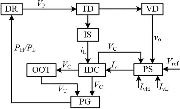
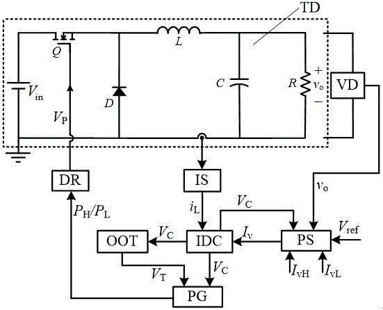
[0027] figure 1 It is shown that a specific embodiment of the present invention is a control method of a switching converter, and its specific method is:

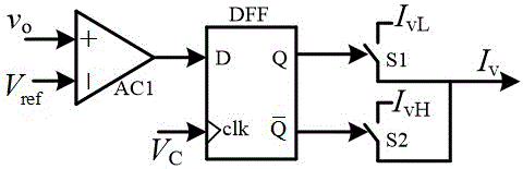
[0028] When the inductor current i L Less than valley current I v , the comparison circuit IDC generates a trigger pulse signal V C , at this time the output voltage detection circuit VD detects the output voltage v of the converter o , and the output voltage v o with reference voltage V ref For comparison: when the output voltage v o less than the reference voltage V ref , the controller selects a high valley current I vH , the inductor current i L It starts to rise from the valley current of the previous switching cycle, and after the one-shot timer OOT counts T on After, the inductor current i L begins to decrease until the high valley current I vH When a switching cycle ends; when the output voltage v o greater than the reference voltage V ref , the controller selects a high valley current I vL , the induc...

Embodiment 2

[0040] Figure 7 It is shown that this example is basically the same as the first example, except that the switching converter TD controlled in this example is a Boost converter.

Embodiment 3

[0042] Figure 8 It is shown that this example is basically the same as the first example, except that the switching converter TD controlled in this example is a Buck-Boost converter.

[0043] The inventive method can be realized with analog device or digital device conveniently; Except the switch converter in the above embodiment, also can be used for Cuk converter, flyback converter, forward converter, half-bridge converter, A switching converter composed of various power circuits such as a full bridge converter.

[0044] Embodiment 1 of the present invention adopts the circuit parameters in Table 1 for simulation.

[0045] Table 1 Simulation parameters of constant on-time control converter with valley current regulation

[0046] name


PUM


Abstract

The invention discloses a valley current regulation constant on-time control method and its device for a continuous conduction mode switching converter: at the initial moment of each switching cycle, according to the output voltage v o with reference voltage V ref The magnitude relationship between selects the effective inductor valley current during the switching period from the preset valley values. The method has simple structure, good dynamic performance, no low-frequency fluctuation phenomenon, and is suitable for switching DC/DC converters of various topological structures.

Description

technical field [0001] The invention relates to a switching converter, in particular to a valley value current regulation constant on-time control method and a device thereof. Background technique: [0002] With the development of power electronics technology and the popularization of portable electronic devices, a novel nonlinear non-linear Discrete Control Method—Pulse Train (PT) Control. The adjustment of the output voltage is realized by adjusting the preset combination of high and low power pulse sequences with the same frequency but different duty ratios. It has the characteristics of simple circuit implementation, fast dynamic response and strong robustness, and is suitable for reliability. A switching power supply system with high requirements. [0003] PT control has been successfully applied in switching converters with inductor current discontinuous conduction mode (DCM), that is, the output voltage increases when high power pulses are applied, and the output vo...

Claims


Application Information

Patent Timeline
Patent Type & Authority Applications(China)
IPC IPC(8): H02M1/08H02M3/155
CPCH02M1/08H02M3/155
Inventor 于东升王龙耿乙森杨杰叶宗彬马草原
Owner CHINA UNIV OF MINING & TECH
Why Eureka
Try Eureka