
Bistable piezoelectric-type multi-directional fluid energy collecting device

A collection device, piezoelectric technology, applied to piezoelectric effect/electrostrictive or magnetostrictive motors, electrical components, generators/motors, etc., can solve the problem of low efficiency of wind energy collection and the intensification of fossil energy in real-time changing direction environment, difficult to achieve self-supply and other issues, to achieve the effect of improving energy utilization efficiency, large fluid energy reserves, and improving complex structures

Active Publication Date: 2016-12-21
HEFEI UNIV OF TECH
View PDF11 Cites 7 Cited by
  • Summary
  • Abstract
  • Description
  • Claims
  • Application Information

AI Technical Summary

Problems solved by technology

[0002] There are two obvious defects in today's energy supply: one is that microelectronic products rely mainly on chemical batteries for energy supply, and it is difficult to achieve self-supply energy; the other is that excessive reliance on non-renewable fossil energy has exacerbated environmental degradation and energy shortage crises
In addition to the complex structure of the above-mentioned rotary piezoelectric wind generator, which requires the conversion of mechanical parts, it is also difficult to drive the blades to rotate to generate electricity when the wind speed is low, and when the generator is installed and fixed, the direction of wind energy collection is fixed. less efficient

Method used


Image

  • Bistable piezoelectric-type multi-directional fluid energy collecting device
  • Bistable piezoelectric-type multi-directional fluid energy collecting device
  • Bistable piezoelectric-type multi-directional fluid energy collecting device

Examples


Embodiment Construction

[0034] See attached picture.

[0035] In order to make the object, technical solution and advantages of the present invention clearer, the present invention will be further described in detail below in conjunction with the accompanying drawings and embodiments. It should be understood that the specific embodiments described here are only used to explain the present invention, not to limit the present invention.

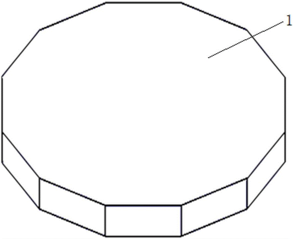
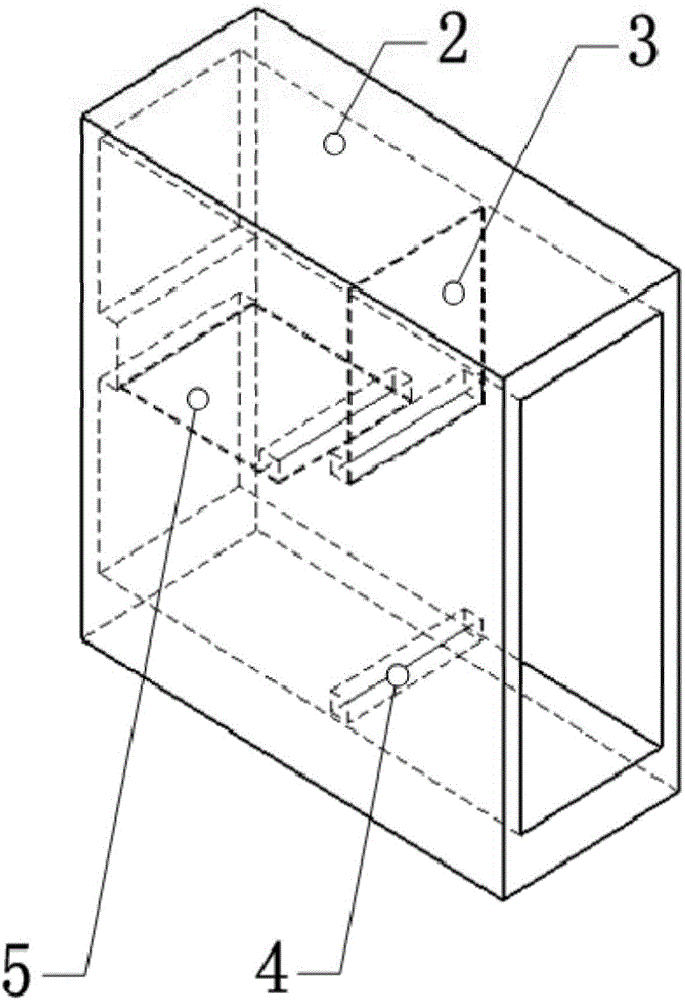
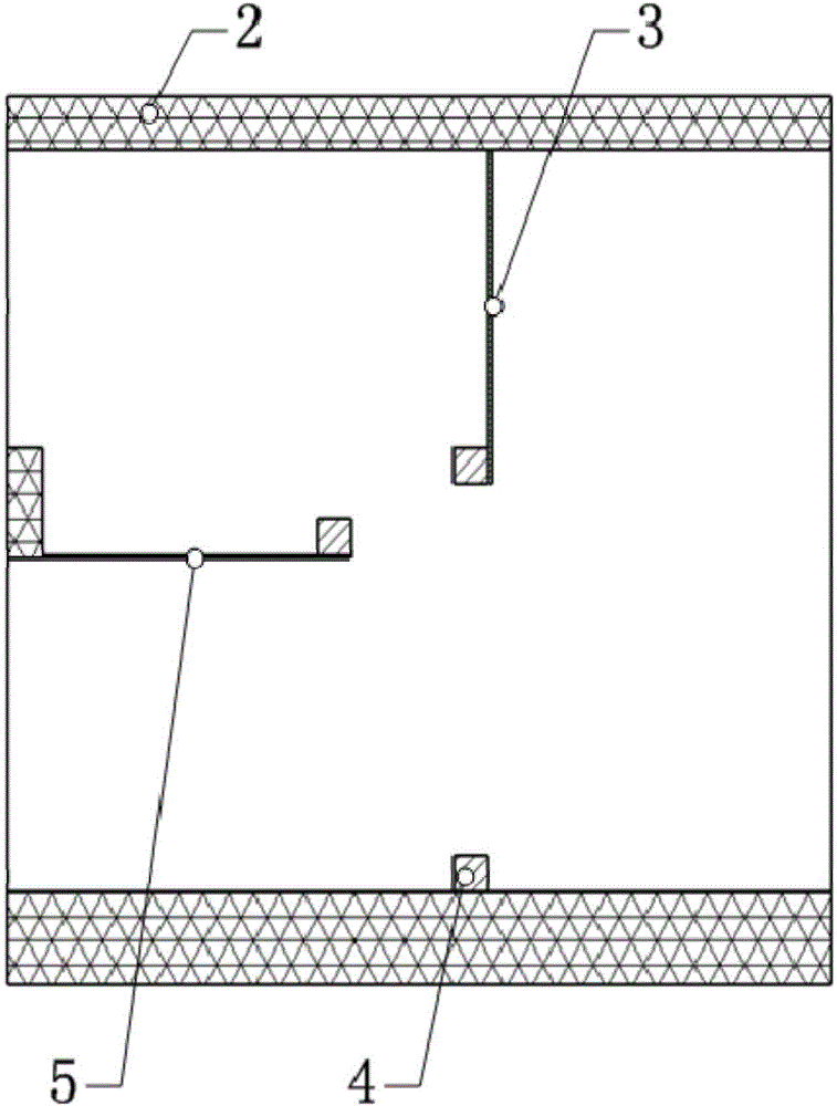
[0036] Figure 5 It is a three-dimensional view of a bistable piezoelectric multidirectional fluid energy collection device according to the present invention. Such as Figure 5As shown in , according to the present invention, the bistable piezoelectric multi-directional fluid energy collection device mainly includes a regular twelve prism base 1, twelve diversion shells 2, twenty-four sheet metal plates 3, twelve The magnetic mass block 4 fixed on the lower surface of the channel of the guide housing, the twenty-four magnetic mass blocks 4 fixed on the free end of...


PUM


Abstract

The invention discloses a bistable piezoelectric-type multi-directional fluid energy collecting device, which comprises a base, wherein the base is of a polyhedral structure; a plurality of diversion shells which are toward different directions are fixed on the base; an outlet surface of a channel in each diversion shell is bonded with the side surfaces of the polyhedral base; two metal sheets are arranged in each diversion shell and are fixed in the vertical surface and the horizontal surface of each diversion shell respectively; flexible piezoelectric films are bonded on the upper surface and the lower surface of each metal sheet respectively; magnetic mass blocks are fixedly arranged at free ends of two metal sheets and on the lower surface of the channel of each diversion shell respectively; and the opposite surfaces of the magnetic mass blocks fixed at the free end of the metal sheet in the vertical surface of each diversion shell, the free end of the metal sheet in the horizontal surface of each diversion shell and on the lower surface of the channel of each diversion shell are the same in polarity. The fluid energy collecting device combines a piezoelectric material with fluid energy for utilization, and has the advantages that a piezoelectric energy collecting device is easy to microminiaturize and integrate, and the fluid energy is high in reserves and renewable.

Description

Technical field: [0001] The invention relates to the technical field of energy recovery and new energy, in particular to a piezoelectric energy harvesting device, in particular to a piezoelectric fluid energy harvesting device with a bistable structure. Background technique: [0002] There are two obvious defects in today's energy supply: one is that microelectronic products rely mainly on chemical batteries for energy supply, making it difficult to achieve self-supply energy; the other is that excessive reliance on non-renewable fossil energy has exacerbated environmental degradation and energy shortage crises. [0003] Moore's law promotes the rapid development of micro-electromechanical technology, and the research and development of small-sized, low-energy-consuming microelectronic devices has made great progress, and chips with semiconductors as the main material have achieved miniaturization and low power consumption. However, at present, most microelectronic products ...

Claims


Application Information

Patent Timeline
IPC IPC(8): H02N2/18
CPCH02N2/185
Inventor 邓华夏王哲敏温亚远张进马孟超于连栋
Owner HEFEI UNIV OF TECH
Learn More