Hybrid filter device and multiplexer

Pending Publication Date: 2020-07-16
MURATA MFG CO LTD
View PDF2 Cites 4 Cited by
  • Summary
  • Abstract
  • Description
  • Claims
  • Application Information

AI Technical Summary

Benefits of technology

[0005]With the increasing miniaturization and multiple band support of mobile communication devices and the like in recent years, there is demand for further miniaturization and higher integration of filter devices. However, for example, in a structure in

Problems solved by technology

However, for example, in a structure in which an acoustic wave device including an acoustic wave resonator and a passive device including an induct

Method used


Image

  • Hybrid filter device and multiplexer
  • Hybrid filter device and multiplexer
  • Hybrid filter device and multiplexer

Examples


Example

Embodiment 1

[1-1. Circuit Configuration of Hybrid Filter Device]

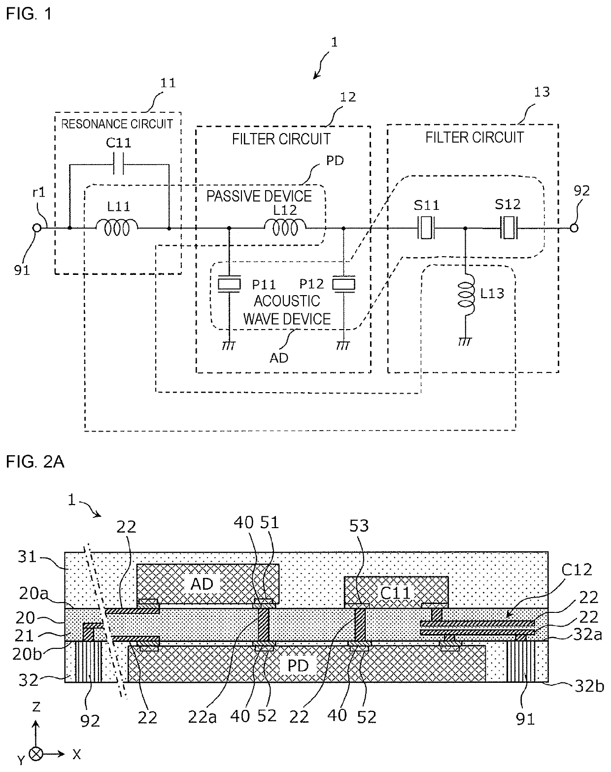
[0023]First, the circuit configuration of a hybrid filter device 1 will be described. FIG. 1 is a circuit configuration diagram of the hybrid filter device 1 according to embodiment 1.

[0024]The hybrid filter device 1 illustrated in FIG. 1 includes a resonance circuit 11, filter circuits 12 and 13, and input / output terminals 91 and 92. The resonance circuit 11 and the filter circuits 12 and 13 are connected in series with each other in this order on a path r1 connecting the input / output terminal 91 and the input / output terminal 92.

[0025]The resonance circuit 11 includes an inductor element L11 and a capacitor element C11. The inductor element L11 is provided on the path r1 and is connected to the input / output terminal 91. The capacitor element C11 is connected in parallel with the inductor element L11. An LC parallel resonance circuit is formed by the capacitor element C11 and the inductor element L11 of resonance circui...

Example

Embodiment 2

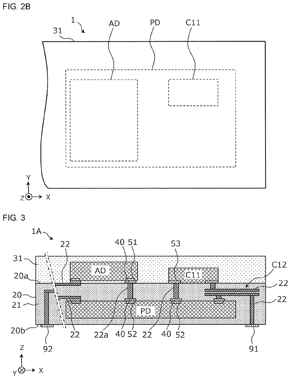
[0054]The structure of a hybrid filter device 1A of embodiment 2 will be described while referring to FIG. 3. The hybrid filter device 1A of embodiment 2 differs from the hybrid filter device 1 of embodiment 1 in that the hybrid filter device 1A has a one surface mounting structure and in that the passive device PD is built into the substrate 20.

[0055]FIG. 3 is a sectional view of the hybrid filter device 1A. As illustrated in FIG. 3, the hybrid filter device 1A includes the substrate 20, the acoustic wave device AD and the capacitor element C11, which are mounted on the one main surface 20a of the substrate 20, and the passive device PD, which is buried inside the substrate 20.

[0056]The sealing resin layer 31 is provided on the one main surface 20a of the substrate 20 so as to cover the acoustic wave device AD and the capacitor element C11. The other main surface 20b of the substrate 20 is used as a mounting surface when mounting the hybrid filter device 1A on a mother ...

Example

Embodiment 3

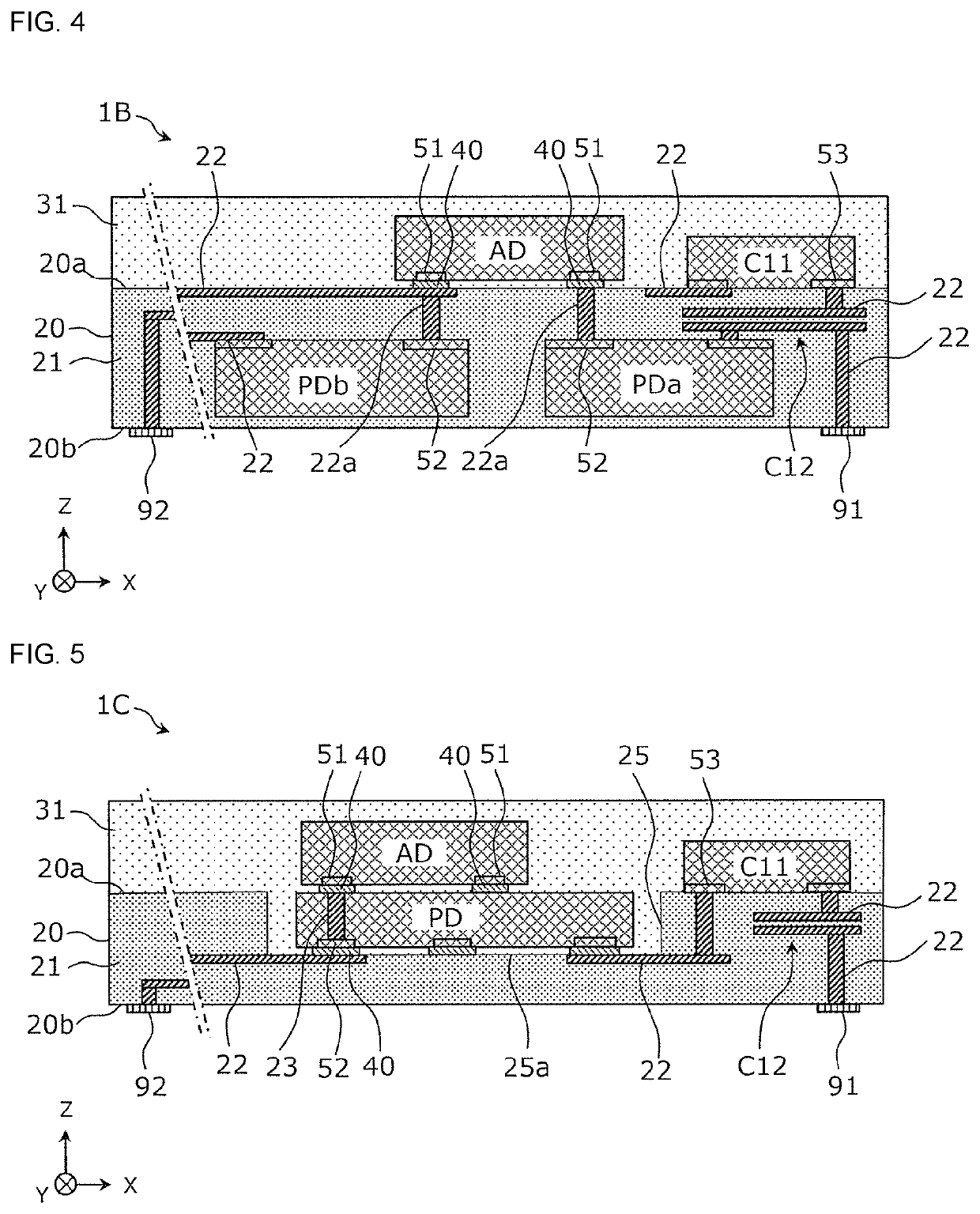
[0064]The structure of a hybrid filter device 1B of embodiment 3 will be described while referring to FIG. 4. The hybrid filter device 1B of embodiment 3 differs from the hybrid filter device 1 of embodiment 1 in that the hybrid filter device 1B has a one surface mounting structure and in that two passive devices PDa and PDb are built into the substrate 20.

[0065]FIG. 4 is a sectional view of the hybrid filter device 1B. As illustrated in FIG. 4, the hybrid filter device 1B includes the substrate 20, the acoustic wave device AD and the capacitor element C11, which are mounted on the one main surface20a of the substrate 20, and the passive devices PDa and PDb, which are buried inside the substrate 20.

[0066]For example, one passive device PDa among the two passive devices PDa and PDb includes the inductor elements L11 and L12 and the other passive device PDb includes the inductor element L13. The passive devices PDa and PDb are multilayer chip inductors or wound wire induct...


PUM


Abstract

A hybrid filter device (1) includes an acoustic wave device (AD) that includes an acoustic wave resonator and a passive device (PD) that includes an inductor element or an inductor element and a capacitance element. At least one of the acoustic wave device (AD) and the passive device (PD) is mounted on a substrate (20) of the hybrid filter device (1) and the acoustic wave device (AD) and the passive device (PD) are electrically connected to each other. The acoustic wave device (AD) overlaps the passive device (PD) when the hybrid filter device (1) is viewed in a direction perpendicular to one main surface (20a) of the substrate (20).

Description

[0001]This is a continuation of International Application No. PCT / JP2018 / 031322 filed on Aug. 24, 2018 which claims priority from Japanese Patent Application No. 2017-192101 filed on Sep. 29, 2017. The contents of these applications are incorporated herein by reference in their entireties.BACKGROUND OF THE DISCLOSUREField of the Disclosure[0002]The present disclosure relates to a hybrid filter device that includes an acoustic wave device including an acoustic wave resonator and a passive device including an inductor element or an inductor element and a capacitance element, and relates to a multiplexer.Description of the Related Art[0003]Heretofore, as a filter device provided in a mobile communication device and the like, a filter device is known that includes an acoustic wave resonator and an inductor element or a capacitance element (for example, refer to Patent Document 1). A filter device consisting of an acoustic wave device including an acoustic wave resonator and a passive de...

Claims


Application Information

Patent Timeline
IPC IPC(8): H03H9/54H03H9/05H03H9/70
CPCH03H9/0557H03H9/542H03H9/70H04B1/18H03H9/0552H03H9/0542H03H9/0566H03H9/605H03H9/6483H03H9/706H03H9/725
Inventor KATO, MASANORI
Owner MURATA MFG CO LTD
Why Eureka
Try Eureka