Flyback LED drive circuit based on BP neural network PI control method

A BP neural network, LED driving technology, applied in the field of LED driving circuit and switching power supply, can solve the problems of low stability, low adaptability, poor adaptability of operating circuit, etc. adaptive effect

Active Publication Date: 2016-12-21
ZHEJIANG UNIV
View PDF6 Cites 8 Cited by
  • Summary
  • Abstract
  • Description
  • Claims
  • Application Information

AI Technical Summary

Problems solved by technology

The former circuit structure is fixed and inflexible, which is not conducive to improving the performance of the circuit.
The circuit structure of the latter is simple and flexible, but the control algorithm commonly used to drive the flyback LED drive circuit cannot achieve the ideal control effect. The parameters are often poorly set, the performance is not good, and the adaptability to the operating circuit is very poor, especially in the case of large input or load changes, there are shortcomings such as insufficient response speed, insufficient stability, and relatively low adaptability

Method used


Image

  • Flyback LED drive circuit based on BP neural network PI control method
  • Flyback LED drive circuit based on BP neural network PI control method
  • Flyback LED drive circuit based on BP neural network PI control method

Examples


Embodiment 1

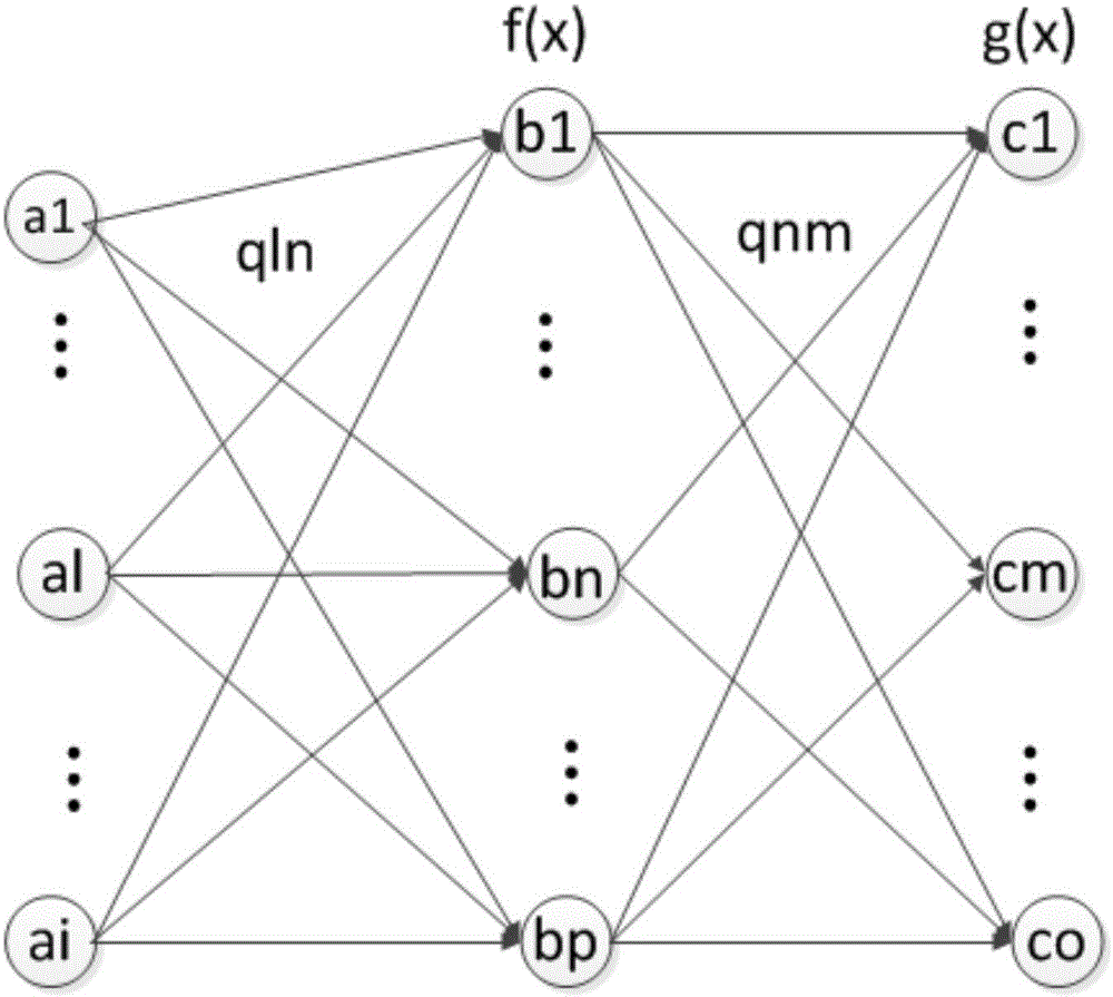
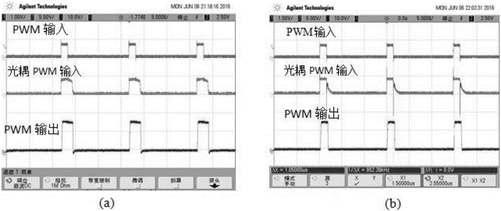
[0046] Take the input AC 220V, the LED load is 20 1W white LED particles connected in series, and the output current r(k) is set to 0.18A. The BP neural network PI control method takes 1 as the number i of input layer nodes, 5 as the number p of hidden layer nodes, and 2 as the number of output layer nodes, corresponding to the P parameter and I parameter in the PI parameters respectively, such as image 3 As shown, the time for the flyback LED drive circuit based on the BP neural network PI control method to output the set current value stably is about 0.01s, and the time for the flyback LED drive circuit with the ordinary PI control method to output the set current value stably is 0.016 s.

[0047] Through this example, the flyback LED drive circuit based on the BP neural network PI control method can be made with a response speed higher than that of the common PI control method.

Embodiment 2

[0049] Take the input AC 220V, the LED load is 20 1W white LED particles connected in series, and the output current r(k) is set to 0.35A. The BP neural network PI control method takes 1 as the number i of input layer nodes, 5 as the number p of hidden layer nodes, and 2 as the number of output layer nodes, corresponding to the P parameter and I parameter in the PI parameters respectively. like Figure 4 The measured output time of the flyback LED drive circuit based on the BP neural network PI control method is 0.016s, and the output time of the flyback LED drive circuit of the ordinary PI control method is 0.025s.

[0050] Through this example, the flyback LED drive circuit based on the BP neural network PI control method can be made with an adaptability higher than that of the common PI control method.

[0051] Thus, the production of the flyback LED drive circuit based on the BP neural network PI control method is completed. The performance of the flyback LED drive circu...


PUM


Abstract

The invention discloses a flyback LED drive circuit based on a BP neural network PI control method. The flyback LED drive circuit comprises an EMI filtering module, a full bridge rectification module, a switch conversion circuit module, a sampling module, a PWM driving module, a processor module and an LED load module, wherein the switch conversion circuit module adopts a flyback topological structure. An embedded processor is utilized to realize the BP neural network PI control method, and the method serves as a flyback LED drive circuit closed-loop control method to realize a network compensation function; and the method has the advantages of fast response speed, high adaptivity, stable closed-loop system, good control effect and low development cost.

Description

technical field [0001] The invention belongs to the field of LED drive circuits, relates to the field of switching power supplies, and in particular designs a flyback LED drive circuit based on a BP neural network PI control method. Background technique [0002] At present, the traditional LED drive circuit generally has two implementation methods, one is to use a dedicated chip to realize the closed-loop control of the circuit, and the other is to use an embedded processor to write an algorithm to realize the closed-loop control of the circuit. The former circuit structure is fixed and inflexible, which is not conducive to improving the performance of the circuit. The circuit structure of the latter is simple and flexible, but the control algorithm commonly used to drive the flyback LED drive circuit cannot achieve the ideal control effect. The parameters are often poorly set, the performance is not good, and the adaptability to the operating circuit is poor. Especially in...

Claims


Application Information

Patent Timeline
Patent Type & Authority Applications(China)
IPC IPC(8): H05B33/08H05B44/00
CPCH05B45/37Y02B20/30
Inventor 周强陈丹
Owner ZHEJIANG UNIV
Why Eureka
Try Eureka