Heat dissipation control method, device and system for electric cabinet

A technology for electrical cabinets and heat dissipation, which is applied to electrical equipment enclosures/cabinets/drawers, electrical components, electrical equipment structural parts, etc. It can solve problems such as control lag and temperature fluctuations, and achieve timely temperature control response and avoidance. The effect of wasting heat dissipation and improving life expectancy

Active Publication Date: 2019-11-29
GREE ELECTRIC APPLIANCES INC
View PDF4 Cites 0 Cited by
  • Summary
  • Abstract
  • Description
  • Claims
  • Application Information

AI Technical Summary

Problems solved by technology

[0006] Embodiments of the present invention provide a heat dissipation control method, device, and system for an electrical cabinet to at least solve the problem that the existing heat dissipation control method for an electric cabinet controls the speed of the cooling fan by detecting the ambient temperature in the electric cabinet. Prone to technical issues with volatility

Method used


Image

  • Heat dissipation control method, device and system for electric cabinet
  • Heat dissipation control method, device and system for electric cabinet
  • Heat dissipation control method, device and system for electric cabinet

Examples


Embodiment 1

[0023] According to an embodiment of the present invention, a method embodiment of a heat dissipation control method for an electrical cabinet is provided. It should be noted that the steps shown in the flow chart of the accompanying drawings can be executed in a computer system such as a set of computer-executable instructions , and, although a logical order is shown in the flowcharts, in some cases the steps shown or described may be performed in an order different from that shown or described herein.

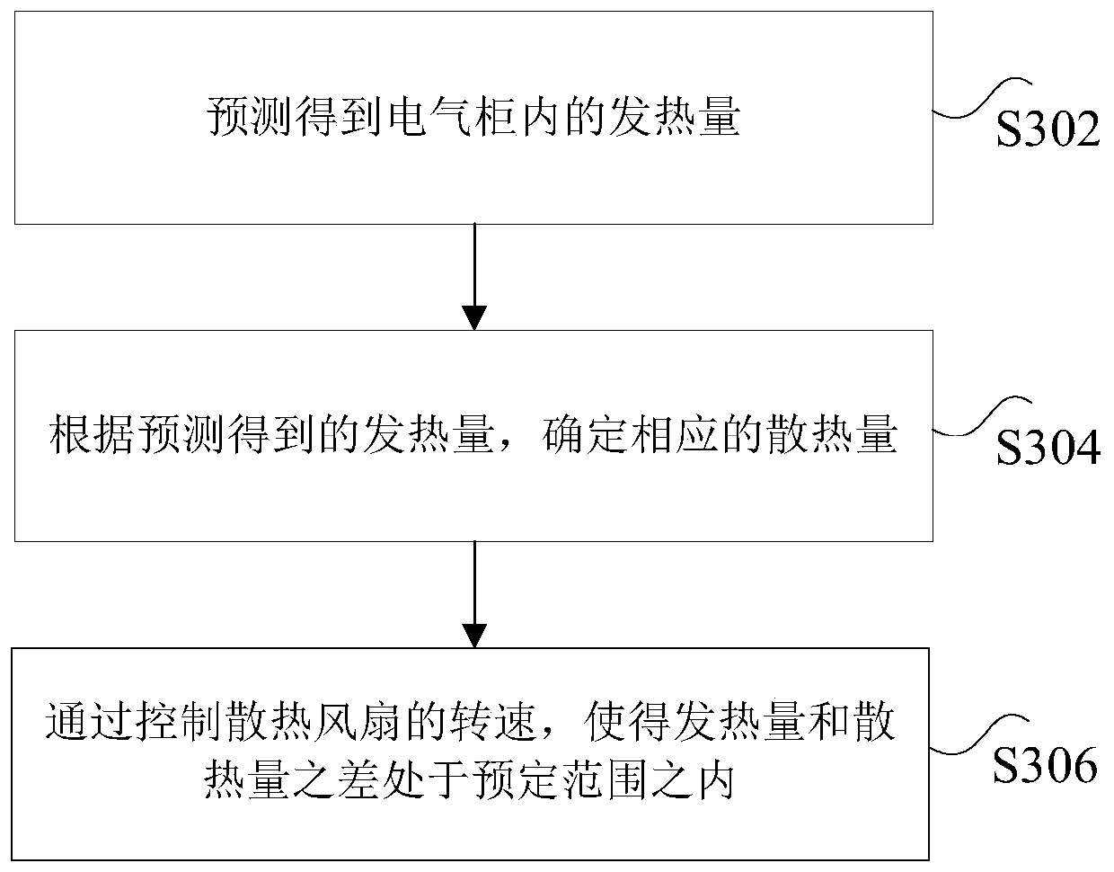
[0024] image 3 It is a flow chart of a heat dissipation control method for an electrical cabinet according to an embodiment of the present invention, such as image 3 As shown, the method includes the following steps:

[0025] Step S302, predicting and obtaining the calorific value in the electrical cabinet.

[0026] Step S304, according to the predicted calorific value, determine the corresponding heat dissipation.

[0027] Step S306, by controlling the rotation speed of...

Embodiment 2

[0077] According to an embodiment of the present invention, a device embodiment of a heat dissipation control device for an electrical cabinet is provided.

[0078] Figure 6 is a schematic diagram of a heat dissipation control device for an electrical cabinet according to an embodiment of the present invention, such as Figure 6 As shown, the device includes:

[0079] The prediction module 62 is used to predict and obtain the calorific value in the electrical cabinet.

[0080] The determination module 64 is configured to determine the corresponding heat dissipation according to the predicted heat generation.

[0081] The control module 66 is configured to control the rotation speed of the heat dissipation fan so that the difference between the calorific value and the heat dissipation value is within a predetermined range.

[0082] Specifically, the above-mentioned predetermined range may be an error range of the calorific value and the heat dissipation amount preset accord...

Embodiment 3

[0086] According to an embodiment of the present invention, a system embodiment of a heat dissipation control system for an electrical cabinet is provided.

[0087] Figure 7 It is a schematic diagram of a heat dissipation control system of an electrical cabinet according to an embodiment of the present invention, such as Figure 7 As shown, the system includes:

[0088] The processor 71 is configured to predict the heat generation in the electrical cabinet, and determine the corresponding heat dissipation according to the predicted heat generation.

[0089] The controller 73 is connected with the processor, and is used to control the rotation speed of the heat dissipation fan so that the difference between the calorific value and the heat dissipation value is within a predetermined range.

[0090] Specifically, the above-mentioned predetermined range may be an error range of the calorific value and the heat dissipation amount preset according to actual needs. For example, w...


PUM


Abstract

The invention discloses a heat dissipation control method, device and system for an electrical cabinet. Among them, the method includes: predicting the amount of heat generated in the electrical cabinet; determining the corresponding amount of heat dissipation based on the predicted amount of heat generation; and controlling the speed of the cooling fan so that the difference between the amount of heat generated and the amount of heat dissipated is within a predetermined range. The invention solves the technical problem that the existing heat dissipation control method of the electrical cabinet controls the rotation speed of the cooling fan by detecting the ambient temperature in the electrical cabinet, but the control is lagging behind and the temperature is prone to fluctuations.

Description

technical field [0001] The present invention relates to the field of electrical cabinets, in particular to a heat dissipation control method, device and system for an electrical cabinet. Background technique [0002] As clean energy, electric energy plays a very important role in industrial production and people's daily life. Various electrical cabinets play an irreplaceable role as terminal equipment for controlling the use of electric energy. However, these electrical cabinets face Among them, the heat generation and heat dissipation of the conductive parts in the electrical cabinet is a typical problem, especially for high-power electrical cabinets. When the high-power electrical cabinet is running, the current is large, and the heat generated is also relatively large, which puts forward higher requirements for the heat dissipation of the electrical cabinet. [0003] The heat dissipation control method widely used at present is generally to detect the ambient temperature...

Claims


Application Information

Patent Timeline
Patent Type & Authority Patents(China)
IPC IPC(8): H05K7/20
CPCH05K7/20209G06F1/206G06F1/20H05K5/0213H05K7/20136
Inventor 刘克勤尤英帅冯重阳
Owner GREE ELECTRIC APPLIANCES INC
Why Eureka
Try Eureka