Radial bearing arrangement in refrigeration compressor

A technology for refrigeration compressors and supports, applied in engine components, pump components, mechanical equipment, etc., can solve problems such as high wear and insufficient lubrication

Active Publication Date: 2016-12-21
EMPRESA BRASILEIRA DE COMPRESSORES SA (EMBRACO)
View PDF8 Cites 0 Cited by
  • Summary
  • Abstract
  • Description
  • Claims
  • Application Information

AI Technical Summary

Problems solved by technology

[0022] Said prior art construction only addresses the maintenance of the oil film into the radial bearings of the replica cold compressor, only taking into account the problem of insufficient lubrication and high wear in the first end 40a of the bearing hub 40

Method used


Image

  • Radial bearing arrangement in refrigeration compressor
  • Radial bearing arrangement in refrigeration compressor
  • Radial bearing arrangement in refrigeration compressor

Examples


Embodiment Construction

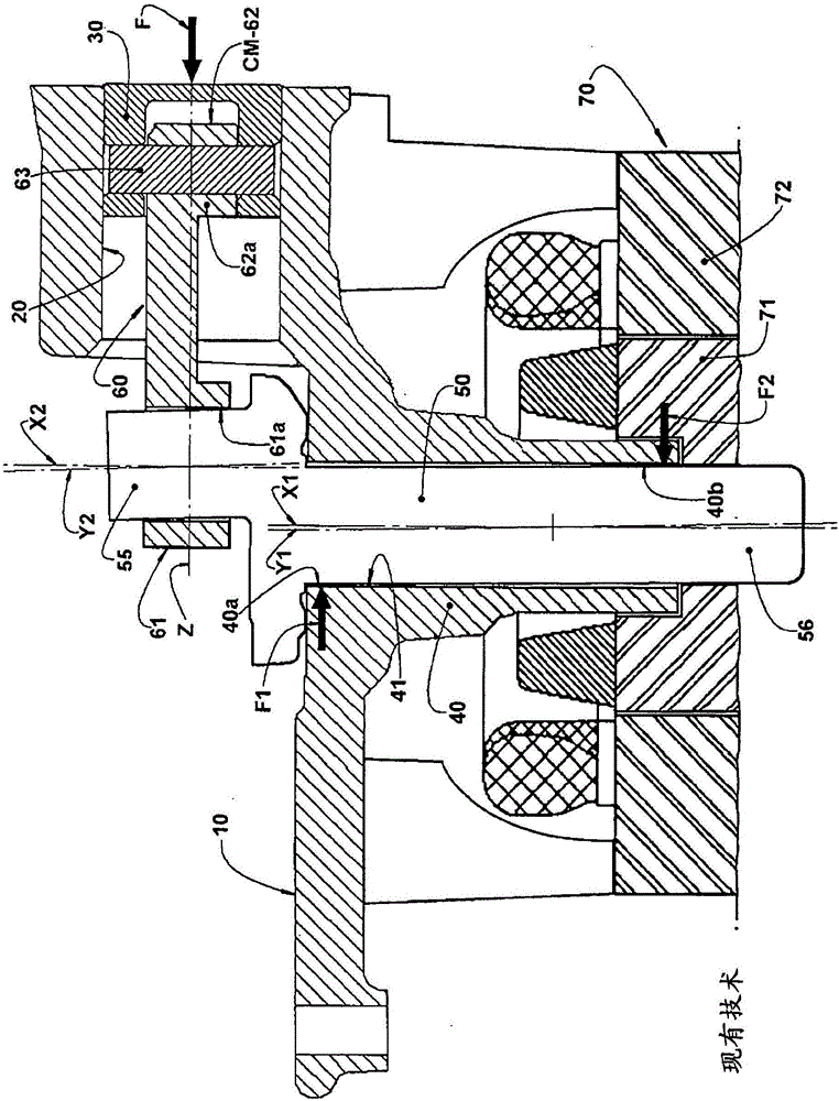
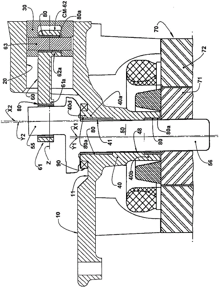
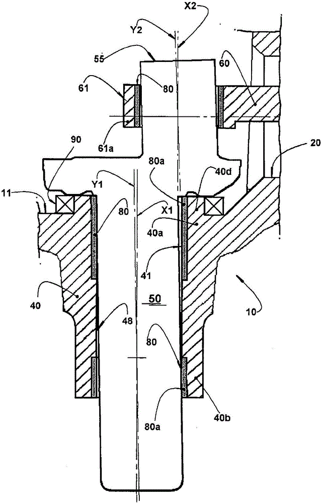
[0040] As mentioned above and shown in the drawings, the type of refrigeration compressor to which the radial support arrangement of the present invention is applied includes a crankcase 10 inside a housing (not shown) in a one-piece or non-one-piece The form bears a support hub 40 internally delimiting a radial support 41 with axis X1 and cylinder 20 with axis Z.

[0041] A crankshaft 50 with an axis Y1 is mounted inside the radial support 41 of the support hub 40 and comprises a free end 56 and an eccentric end 55 with an axis Y2 extending from the first end of the support hub 40 A portion 40a protrudes outward, and a free end protrudes outward from a second end portion 40b of the support hub 40 .

[0042] The piston 30 is housed in the cylinder 20 so as to be moved in a reciprocating manner within the cylinder by a connecting rod 60 having an end defining a larger aperture 61 and carrying coupling means CM to allow coupling of the connecting rod 60 to the opening of the pis...


PUM


Abstract

A compressor comprises a bearing hub (40) defining a radial bearing (41) having a first and a second end portion (40a, 40b) and supporting a crankshaft (50) having an eccentric end portion (55) supporting the larger eye (61) of a connecting rod (60) coupled to the piston (30), for example, by a smaller eye (62) mounted around a piston pin (63). The second end portion (40b) and, optionally, the first end portion (40a) of the bearing hub (40) and the larger and smaller eyes (61, 62) of the connecting rod (60) are internally provided with bushings (80). End portions (40a, 40b) of the bearing hub (40) and of the larger and smaller eyes (61, 62) may have their structure resistant to the pressing of a confronting compressor component supported on the end portions, or further have a terminal portion (40c, 40d, 61a, 62a) elastically deformable together with a confronting terminal portion of the associated bushing (80).

Description

technical field [0001] The present invention relates to a radial bearing arrangement between parts of a hermetic or non-hermetic reciprocating refrigeration compressor capable of relative movement in rotational or angular motion relative to each other in order to reduce said The coefficient of friction between components, thereby reducing the starting torque and power consumption of the motor. The invention is particularly applicable to the radial support of the crankshaft and the radial support of the large and small holes of the connecting rods of a compressor of the type considered here. [0002] The present invention also allows that the radial bearing regions may optionally undergo controlled deformation so as to minimize localized or linear contact of cooperating parts caused by alignment errors during fabrication or assembly of said cooperating parts. Caused either by the motor operation of the compressor or by the forces acting on said components from the compression ...

Claims


Application Information

Patent Timeline
Patent Type & Authority Applications(China)
IPC IPC(8): F04B39/00F04B39/02
CPCF04B39/0094F04B39/02F16J1/14
Inventor A·L·曼克R·普夫D·萨科莫里
Owner EMPRESA BRASILEIRA DE COMPRESSORES SA (EMBRACO)
Why Eureka
Try Eureka