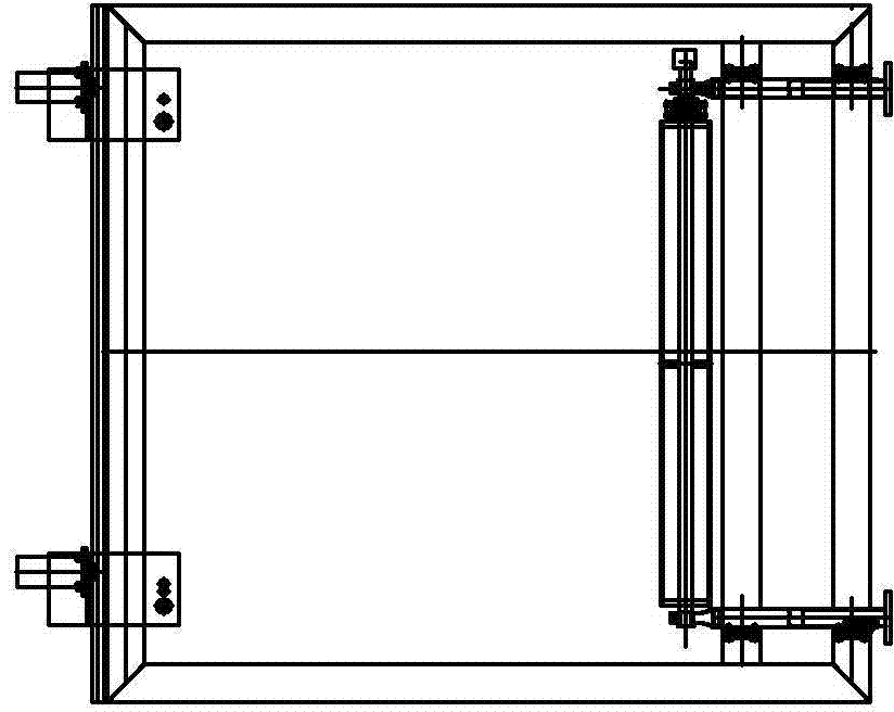
Full-automatic wood feeder
A fully automatic, wood technology, applied in conveyors, loading devices, conveyor objects, etc., can solve the problems of low production efficiency, inability to realize automatic production, and high labor intensity of operators, so as to improve work efficiency and save quantity. , The effect of reducing the process of manual handling
- Summary
- Abstract
- Description
- Claims
- Application Information
AI Technical Summary
Problems solved by technology
Method used
Image
Examples
specific Embodiment approach 1
[0007] Specific implementation mode one: combine Figure 1 to Figure 8 Describe this embodiment mode, a kind of fully automatic timber loading machine described in this embodiment mode comprises conveying mechanism 1, elevating mechanism 2, feeding mechanism 3, dialing mechanism 4, gate-shaped frame 5 and control box, conveying mechanism 1, elevating mechanism 2 and the material shifting mechanism 4 are arranged in sequence along the length direction, and the glyph frame 5 is vertically fixed at the junction of the conveying mechanism 1 and the lifting mechanism 2, and the mounting beam 5-1 of the glyph frame 5 is provided with a feeding mechanism 3, and the conveying mechanism 1. The lifting mechanism 2, the feeding mechanism 3 and the feeding mechanism 4 are respectively connected to the control box through the power cord.
specific Embodiment approach 2
[0008] Specific implementation mode two: combination Figure 1 to Figure 4 Describe this embodiment, the conveying mechanism 1 described in this embodiment includes a conveying motor 1-1, a conveying platform 1-2, a plurality of conveying roller shafts 1-3 and a plurality of first double sprockets 1-4, and a plurality of conveying rollers Shafts 1-3 are arranged in parallel along the length direction of conveying table 1-2, and the two ends of each conveying roller shaft 1-3 are respectively connected to the conveying table 1-2 through bearings, and the same The first double sprocket 1-4 is arranged on the end, and the conveying motor 1-1 is arranged on one side of the conveying platform 1-2, and a conveying roller shaft 1-3 on the conveying platform 1-2 and the conveying motor 1-1 connected, two adjacent conveying roller shafts 1-3 are respectively connected through the first chain drive. Other compositions and connection methods are the same as those in Embodiment 1.
specific Embodiment approach 3
[0009] Specific implementation mode three: combination figure 1 , figure 2 , image 3 with Figure 5 Describe this embodiment, the lifting mechanism 2 described in this embodiment includes a hydraulic lifting platform 2-1, a lifting motor, a lifting roller shaft motor 2-2 and a plurality of lifting roller shafts 2-3, and the hydraulic lifting platform 2-1 is a scissors type hydraulic lifting platform 2-1, the lifting motor is connected with the hydraulic lifting platform 2-1, and a plurality of lifting roller shafts 2-3 are arranged in parallel in sequence along the length direction of the hydraulic lifting platform 2-1, and each lifting roller shaft 2-3 The two ends are connected in rotation with the hydraulic lifting platform 2-1 through bearings respectively, and the same end of each lifting roller shaft 2-3 is provided with a second double sprocket 2-4, and the lifting roller shaft motor 2-2 is arranged on the hydraulic lifting platform 2-1. On one side of the platform...
PUM
 Abstract
Description
Claims
Application Information
 - R&D
- Intellectual Property
- Life Sciences
- Materials
- Tech Scout
- Unparalleled Data Quality
- Higher Quality Content
- 60% Fewer Hallucinations
Browse by: Latest US Patents, China's latest patents, Technical Efficacy Thesaurus, Application Domain, Technology Topic, Popular Technical Reports.
© 2025 PatSnap. All rights reserved.Legal|Privacy policy|Modern Slavery Act Transparency Statement|Sitemap|About US| Contact US: help@patsnap.com


