Piezoelectric self-energized luminous umbrella

A self-powered, piezoelectric power generation technology, applied in the field of luminous umbrellas, can solve the problems of small power generation, low metal coil swing speed, small coil size, etc.

Active Publication Date: 2017-01-04
ZHEJIANG UNIV
View PDF4 Cites 1 Cited by
  • Summary
  • Abstract
  • Description
  • Claims
  • Application Information

AI Technical Summary

Problems solved by technology

[0007] The disadvantage of this generator umbrella is that the size of the coil it uses is small, and the swing rate of the metal coil is not large, which will result in a small amount of power generation, which may not be able to meet the voltage required for battery power generation.

Method used


Image

  • Piezoelectric self-energized luminous umbrella
  • Piezoelectric self-energized luminous umbrella
  • Piezoelectric self-energized luminous umbrella

Examples


Embodiment Construction

[0031] The present invention will be described in further detail below in conjunction with the accompanying drawings and specific embodiments.

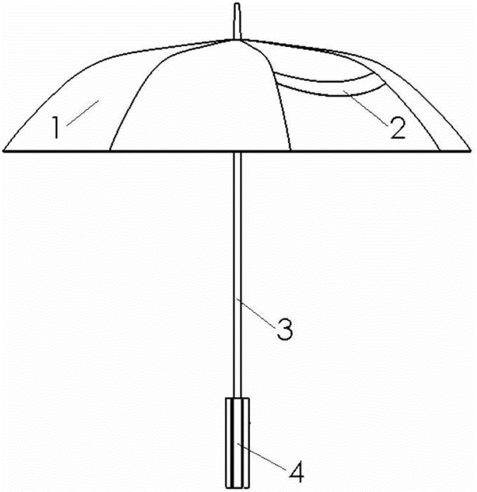
[0032] like figure 1 As shown, a piezoelectric self-powered luminous umbrella in this embodiment includes an umbrella surface 1, a light emitting device 2, an umbrella handle 3 and an umbrella handle 4, and the umbrella handle 4 and the umbrella handle 3 as well as the umbrella handle 3 and the umbrella surface 1 all adopt threads The way to connect.

[0033] A light emitting device 2 is arranged on the umbrella surface 1, and the light emitting device 2 is a cold light sheet, which is composed of figure 1 It can be seen that the installation method of the light emitting device 2 on the umbrella surface 1 is adhesive bonding.

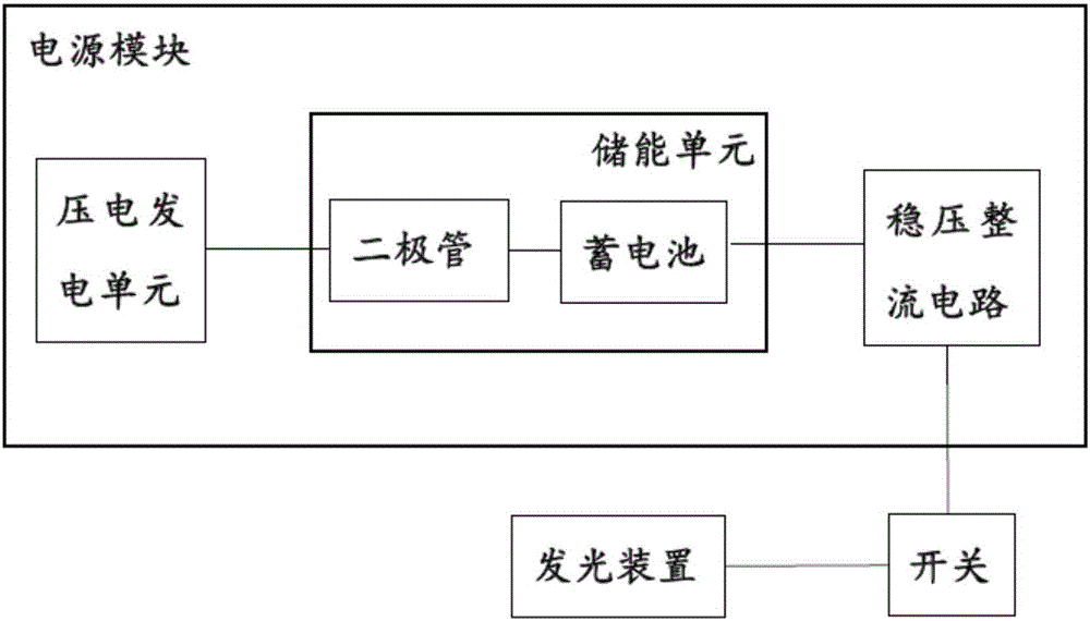
[0034] A power supply module is installed in the umbrella handle 4, such as figure 2 As shown, the power module includes a piezoelectric generating unit, an energy storage unit and a voltage stabilizing rec...


PUM


Abstract

The invention discloses a piezoelectric self-energized luminous umbrella. The piezoelectric self-energized luminous umbrella comprises an umbrella handle and an umbrella fabric, wherein a power supply module and a control module are arranged in the umbrella handle, the umbrella fabric is provided with a luminous apparatus, the power supply module comprises a piezoelectric power generation unit and an energy storage unit, two sides of the umbrella handle are provided with an extrusion deformation zone, the piezoelectric power generation unit comprises a piezoelectric body matched with the extrusion deformation zone in a contact manner and a limiting body controlling a deformation direction of the power generation unit, and the piezoelectric body is arranged at two sides of the umbrella handle and connected with the energy storage unit. Two sides of the umbrella handle are extruded by an umbrella bearer, an umbrella handle shell drives the piezoelectric body to be deformed, and the piezoelectric body generates different electric charges in the deformation process to generate a potential difference, thereby charging the energy storage unit. The luminous apparatus can be started only by turning on a switch.

Description

technical field [0001] The invention relates to a luminous umbrella, in particular to a piezoelectric self-powered luminous umbrella. Background technique [0002] For a long time, pedestrians frequently have traffic accidents in rainy nights. Drivers cannot see or see pedestrians clearly is one of the important reasons. One solution to this problem is to allow pedestrians to identify themselves prominently in rainy nights. In view of the fact that pedestrians need to hold umbrellas in rainy nights, an umbrella that can warn will be a better solution. At present, the product of luminous umbrella can be seen in the market. [0003] But the effect of the luminous umbrella on the market is mainly to decorate attractive in appearance, and the energy supply mode mostly is battery power supply. The main problem of using batteries for power supply is the trouble of disassembling and assembling the batteries: 1. Because the batteries consume power even when the load is not working...

Claims


Application Information

Patent Timeline
Patent Type & Authority Applications(China)
IPC IPC(8): A45B25/00A45B25/18A45B3/00A45B3/04A45B9/02H02N2/18
CPCA45B3/00A45B3/04A45B9/02A45B25/00A45B25/18A45B2200/1009A45B2200/1018A45B2200/1081H02N2/186
Inventor 姚鑫骅兰刘健栾丛丛傅建中
Owner ZHEJIANG UNIV
Why Eureka
Try Eureka