Cooking method

A pot body and material technology, applied in cooking utensils, household utensils, applications, etc., can solve the problems of difficult heat conduction, low heating and cooking efficiency, large thermal resistance, etc., to increase the heat transfer area, improve heating efficiency, The effect of rapid heat transfer process

Inactive Publication Date: 2017-01-04
华小玲
View PDF10 Cites 0 Cited by
  • Summary
  • Abstract
  • Description
  • Claims
  • Application Information

AI Technical Summary

Problems solved by technology

[0005] In the process of using the above cooking equipment for cooking, if Figure 12 As shown, although the rotation of the pot body 30 will drive the cooking material 30 ′ to turn over in the pot, the cooking material is still basically distributed in a stacked manner at the bottom of the pot body, and only a small part of the cooking material is in direct contact with the pot body. The contact area between the material and the pot body is less than 40% of the surface area of ​​the inner wall of the pot, so the cooking material can only be heated in a cumulative manner, and at the same time, only a small interaction between the cooking material and the cooking material and the pot body Forces contact each other, and the thermal resistance is large, which makes it difficult to conduct heat to the cooking materials far away from the inner wall of the pot, making the cooking materials heated unevenly, and the heating and cooking efficiency is low
Although the stirring mechanism is used to stir the cooking materials to increase the chances of the materials in different positions in the pot and the surfaces of the materials contacting the pot body, the stirring mechanism cannot eliminate the accumulation state of the materials, and it is difficult to effectively carry out the core of the accumulated materials. Stir-frying, and then can not effectively improve the lack of uneven heating of cooking materials and low heating efficiency
Moreover, using a stirring mechanism to stir will also cause the cooking materials to be subjected to a large extruding force, which makes it difficult to maintain the integrity of the shape of the raw materials, and cannot meet the "shape" requirements of Chinese dishes.
In addition, in order to meet the requirements of fast frying in hot pots, larger pot bodies are required to increase the contact area between cooking materials and pot bodies when using the above cooking equipment for cooking, so as to improve the heating efficiency, which in turn leads to cooking equipment There is a lack of bulk

Method used


Image

  • Cooking method
  • Cooking method
  • Cooking method

Examples


Embodiment 1

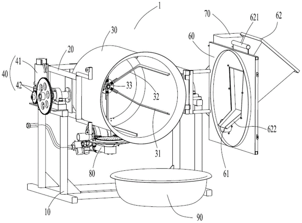
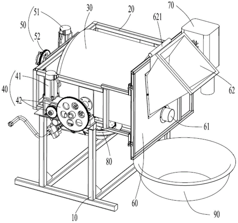
[0063] Such as Figure 1-2 As shown, the cooking system 1 in this embodiment includes a controller (not shown in the figure), a main body support 10, a pot body support 20 rotatably arranged on the main body support 10, and a pot body support 20 rotatably arranged on the pot body support 20. The pot body 30 on the top, the angle adjustment device 40 arranged on the main body support 20, the rotary drive device 50 arranged on the pot body support 20, the pot cover 60 which can be opened and closed on the pot body support 20, the pot cover 60 arranged on the pot The hot air heating device 70 on the cover 60 , the gas heating device 80 which is arranged under the pot body 30 and heats the pot body 30 , and the vegetable output device 90 .

[0064] The pot body 30 is a barrel-shaped pot body with a circular inner circumference in cross section, its main body has approximately the same inner diameter, a pot mouth is formed at the front end, and a hollow pot body extending on the ro...

Embodiment 2

[0076] Such as Image 6 As shown, in this embodiment, the pot body 130 is rotatably disposed on the pot body support 120 , and a conical feature 131 inclined toward the rotation axis of the pot body 130 is formed at one end of the pot body near the mouth of the pot body. The rotating shaft of the pot body is connected with the gear transmission mechanism 152, and the motor 151 drives the pot body 130 to rotate around its rotation axis through the gear transmission mechanism 52.

[0077] see Image 6 with 7 , the inner wall of the pot body 130 is provided with six ribs 132 distributed in an annular array, and the ribs 132 extend continuously between two longitudinal ends of the pot body 130 along the rotation axis of the pot body 130 . Inside the pot body 130 are disposed six scraping pieces 134 that can move linearly back and forth along the rotation axis of the pot body 130 , and each scraping piece 134 is respectively arranged between adjacent ribs 132 . The scraper 134 e...

Embodiment 3

[0084] Such as Figure 8 As shown, in this embodiment, the pot body 230 is provided with a scraper 231 that can expand and contract along its radial direction, and the scraper 231 is between the two longitudinal ends of the pot body 230 along the direction of the rotation axis of the pot body 230 Continuously extending, one end away from the mouth of the pot is fixedly connected with the sliding rod 232 . The sliding rod 232 is slidably installed on the fixing base 233 , and the fixing base 233 is fixedly installed in the pot body 230 . The longitudinal end of the sliding rod 232 abuts against the cam 243, and the cam 243 is connected with the gear transmission mechanism 242 via the rotating shaft passing through the rotating shaft of the pot body. 230 radial telescoping. In the extended state, the scraping member 231 is closely adjacent to the inner wall of the pot body 230 at approximately the highest point of the rotation track of the pot body, and in the retracted state,...


PUM


Abstract

The invention provides a cooking method, which comprises the following steps: (1) putting cooking materials into a bucket type pot body, controlling an included angle between the rotating axis and the horizontal plane to be greater than 0 degrees and smaller than 20 degrees, and inclining the pot body at the state of upward pot opening; (2) controlling the pot body to rotate around the rotating axis at the first rotating speed greater than or equal to critical rotating speed, so that the cooking materials are adhered on the pot body and do rotating motion along with the pot body; and (3) frying the cooking materials. By utilizing the cooking method, not only can the fast and uniform heating on the cooking materials be realized, but also the cooking yield can be effectively improved.

Description

technical field [0001] The invention relates to a cooking method; more specifically, the invention relates to a cooking method for stir-frying. Background technique [0002] Stir-frying is the process of frying cooking materials in a pot. Its main feature is that it requires a hot pot to be fried quickly, so that the cooking materials are heated quickly and evenly, so as to achieve crisp, tender, fresh and fragrant effects. At present, people have developed automatic / semi-automatic cooking systems that can replace or reduce manual operations and have a cooking function. [0003] Chinese patent 200810029877.8 discloses a cooking device, which includes a bracket, a pot body arranged on the bracket, and a rotating mechanism and a turning mechanism arranged on the bracket; the pot body is a barrel-shaped or spherical pot body with an opening at the end , there is a stirring mechanism for stirring inside; the rotating mechanism is connected with the pot body, driving the pot bod...

Claims


Application Information

Patent Timeline
Patent Type & Authority Applications(China)
IPC IPC(8): A47J27/00A47J36/00
Inventor 华小玲
Owner 华小玲
Why Eureka
Try Eureka