Eureka AIR delivers breakthrough ideas for toughest innovation challenges, trusted by R&D personnel around the world.

Double-speed telescopic double-drive locating system

A positioning system and double-speed technology, applied in positioning devices, manipulators, metal processing equipment, etc., can solve the problems that the load beam is difficult to meet the work requirements, takes a long time, and has low work efficiency, and achieves a perfect balance of diversity, beautiful appearance, The effect of improving work efficiency

Inactive Publication Date: 2017-01-04
SHENYANG ZHONGTUO ROBOT EQUIP
View PDF0 Cites 0 Cited by
  • Summary
  • Abstract
  • Description
  • Claims
  • Application Information

AI Technical Summary

Problems solved by technology

[0003] Shortcomings of the prior art: 1. At present, the prior art is all through two motors, one realizes the linear motion of the telescopic beam, and the other motor realizes the linear motion of the manipulator, or one motor controls the linear motion of the telescopic beam, and Another motor rotates the telescopic beam to realize the function from the grabbing position of the stamping part to the lowering position
[0004] 2. Because two motors are needed, if two motors are used, it will not only consume power, but also add a lot of limit and sensors, which will generate a lot of cost, and increase the matching cables, and increase the load, which is not beautiful
Second, if the structure of the rotating telescopic beam is adopted, in terms of safety, the speed of the rotating telescopic beam will be greatly reduced, which will lead to long occupation time, low work efficiency and increased cost
[0005] 3. For the case of large load, the existing load-bearing beam is difficult to meet the work requirements

Method used


Image

  • Double-speed telescopic double-drive locating system
  • Double-speed telescopic double-drive locating system
  • Double-speed telescopic double-drive locating system

Examples


Embodiment Construction

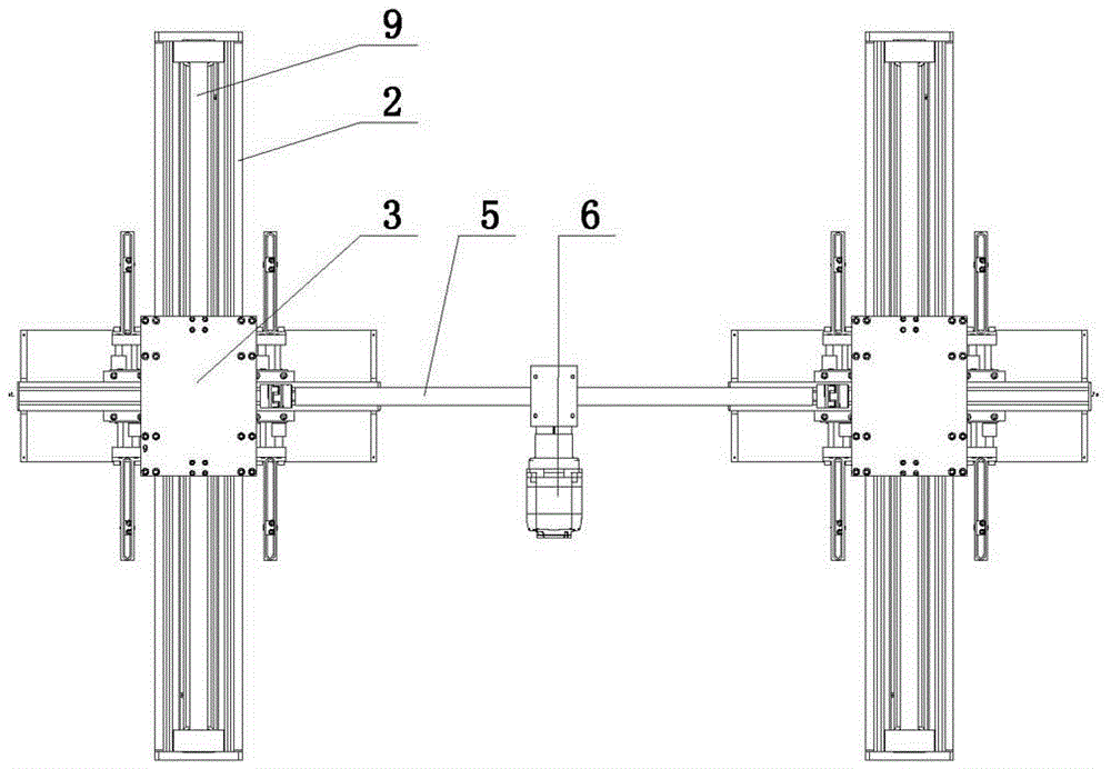
[0020] The present invention comprises two load-bearing beams 2, and is characterized in that: the side of two load-bearing beams 2 is provided with driving rack 11; Between two load-bearing beams 2, drive motor 6 is arranged, and the gears at both ends of synchronous shaft 5 on drive motor 6 12 respectively meshes with the racks 11 on the sides of the two load beams 2; the upper slide plate 3 is arranged above the load beam 2, and the upper slide plate 3 is connected with the synchronous shaft 5 through the connecting plate 10; A synchronous belt 9 is arranged, and the top of the synchronous belt 9 links to each other with the described upper slide plate 3;

[0021] As a preferred solution of the present invention, the connecting plate 10 is provided with a short shaft 8 , the gear 12 is provided at one end of the short shaft 8 , and the synchronous shaft 5 is connected with the short shaft 8 through a coupling 7 .

[0022] Upper guide rails 14 are arranged on both sides of t...


PUM


Abstract

The invention provides a double-speed telescopic double-drive locating system, belongs to the technical field of automatic loading and unloading Cartesian robots of automobile punching parts, and specifically relates to a double-speed telescopic double-drive locating system. The invention provides a double-speed telescopic double-drive locating system which has small occupied space and high working efficiency, and can bear a larger load. The double-speed telescopic double-drive locating system provided by the invention comprises two bearing beams, wherein driving gear racks are arranged on the sides of the two bearing beams; a drive motor is arranged between the two bearing beams, and gears on both ends of a synchronous shaft on the drive motor are respectively engaged with the gear racks on the sides of the two bearing beams; an upper sliding plate is arranged above the bearing beams, and the upper sliding plate is connected with the synchronous shaft via a connecting plate; synchronous belts are arranged in the bearing beams via synchronous belt pulleys, and upper parts of the synchronous belts are connected with the upper sliding plate; and lower parts of the synchronous belts are connected with a lower sliding plate, and a mechanical arm is arranged on the lower sliding plate.

Description

technical field [0001] The invention belongs to the technical field of Cartesian coordinate robots for automatic loading and unloading of automobile stamping parts, and in particular relates to a double-speed telescopic double-drive positioning system. Background technique [0002] At present, in the field of rectangular coordinate robots, the application of long-distance press loading and unloading almost always adopts the method of docking two manipulators. One manipulator picks up the workpiece on the material table and runs to the middle position, and the other manipulator picks up the workpiece. Take it and send it to the press. [0003] Shortcomings of the prior art: 1. At present, the prior art is all through two motors, one realizes the linear motion of the telescopic beam, and the other motor realizes the linear motion of the manipulator, or one motor controls the linear motion of the telescopic beam, and Another motor rotates the telescopic beam to realize the fun...

Claims


Application Information

Patent Timeline
Patent Type & Authority Applications(China)
IPC IPC(8): B21D43/10B21D43/18B25J11/00
CPCB21D43/105B21D43/18B25J11/005
Inventor 杨树彬
Owner SHENYANG ZHONGTUO ROBOT EQUIP
Why Eureka
Eureka Blog
Learn More