Ball electric spindle

A technology of electric spindles and balls, applied in the field of electric spindles, can solve problems affecting the normal operation of equipment, component wear, hazards, etc., and achieve the effect of improving product stability and service life and avoiding friction

Inactive Publication Date: 2017-01-04
深圳市爱贝科精密工业股份有限公司
View PDF6 Cites 6 Cited by
  • Summary
  • Abstract
  • Description
  • Claims
  • Application Information

AI Technical Summary

Problems solved by technology

However, usually, the push rod and the pull rod are directly connected, or only the push rod is used to push the pull rod, resulting in friction between the pull rod and the push rod after the tool is l

Method used


Image

  • Ball electric spindle
  • Ball electric spindle
  • Ball electric spindle

Examples


Example Embodiment

[0022] The present invention will be described in more detail below with reference to the drawings and embodiments.

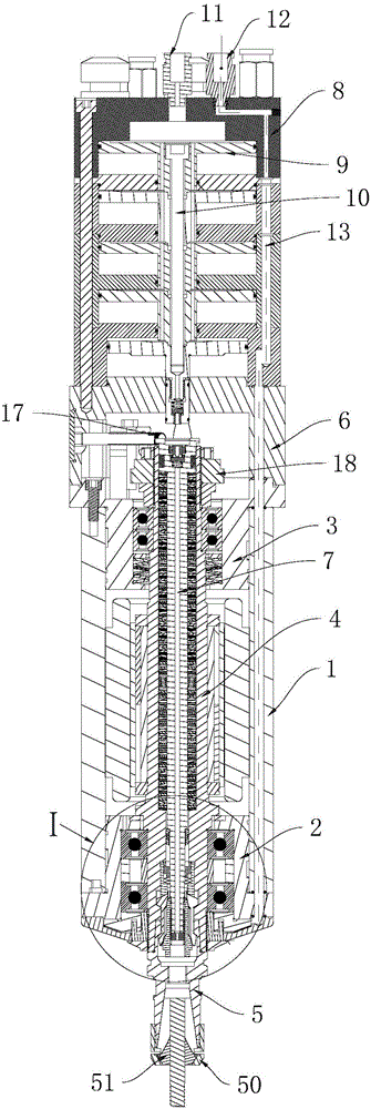
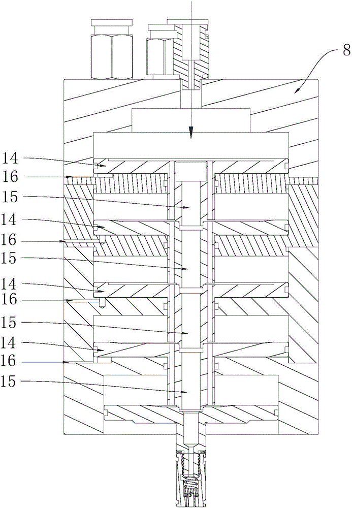
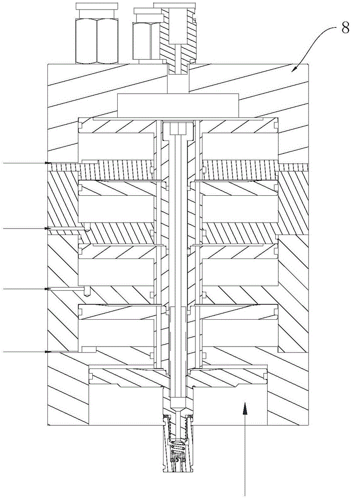
[0023] The invention discloses a ball electric spindle, which combines Figure 1 to Figure 3 As shown, it includes a steel cylinder 1, the front end of the steel cylinder 1 is provided with a front bearing seat assembly 2, and the rear end of the steel cylinder 1 is provided with a rear bearing seat assembly 3, the front bearing seat assembly 2 and the rear A rotor assembly 4 is penetrated between the bearing seat assembly 3, the front end of the rotor assembly 4 is provided with a knife handle 5, and the rear end of the steel cylinder 1 is fixed with a back cover 6 covering the rear bearing seat assembly 3. The center of the rotor assembly 4 is provided with a pull rod 7 for pushing and pulling the knife handle 5. The rear end of the pull rod 7 extends into the back cover 6, and a sleeve 8 is fixed on the back cover 6, and the sleeve 8 A piston assembly 9 is prov...


PUM


Abstract

The invention discloses a ball electric spindle. The ball electric spindle comprises a steel barrel and a rotor assembly, a cutter handle is arranged at the front end of the rotor assembly, a back cover is fixed to the back end of the steel barrel, a pull rod is arranged at the center of the rotor assembly, a sleeve is fixed to the back cover, and a piston assembly is arranged in the sleeve; a push rod assembly is arranged at the center of the piston assembly and is aligned with the pull rod, a first air inlet and a second air inlet are formed in the top of the sleeve, and the first air inlet is formed in the back side of the piston assembly; an air flue is formed in the sleeve and used for communicating the second air inlet and the front side of the piston assembly; when compressed air is injected into the first air inlet, the piston assembly is pushed by the compressed air, the push rod assembly is driven to apply push force to the pull rod, and the pull rod pushes out the cutter handle outwards; and when the compressed air is injected into the second air inlet, the piston assembly is pushed to move backwards, and the push rod assembly is driven to be separated from the pull rod. By means of the ball electric spindle, friction can be effectively prevented from being generated between the pull rod and the push rod, and the improvement of the product stability and the prolonging of the service life are facilitated.

Description

technical field [0001] The invention relates to an electric spindle, in particular to a ball electric spindle. Background technique [0002] When the electric spindle is in use, it usually involves the steps of loading or dismounting the tool. In the above process, the tool handle is usually pushed and pulled under the cooperation of the pull rod and the push rod to complete the tool loading and unloading. However, usually, the push rod and the pull rod are directly connected, or only the push rod is used to push the pull rod, resulting in friction between the pull rod and the push rod after the tool is loaded or even during the operation of the electric spindle, not only It will affect the normal operation of the equipment, and will also cause wear and tear of components, which will cause many hazards. Contents of the invention [0003] The technical problem to be solved by the present invention is to provide an electric spindle that can effectively avoid the friction be...

Claims


Application Information

Patent Timeline
IPC IPC(8): B23B19/02B23Q3/157
CPCB23Q1/70B23Q3/157
Inventor 杨丹群李存杰农乃昌唐良伟
Owner 深圳市爱贝科精密工业股份有限公司
Why Eureka
Try Eureka