Method for processing helical surface of toroidal worm by numerically controlled lathe

A technology of CNC lathes and toroidal worms, applied in worms, components with teeth, belts/chains/gears, etc., can solve the problem of high professional requirements for tool sharpening, not arc thread tooth surface, worm tooth pitch accumulation error Increase and other problems to achieve the effect of simplifying the control method of the machine tool, ensuring the accuracy of the tooth surface, and stabilizing the numerical control system

Active Publication Date: 2017-01-04
SINOSTEEL XIAN MACHINERY
View PDF11 Cites 15 Cited by
  • Summary
  • Abstract
  • Description
  • Claims
  • Application Information

AI Technical Summary

Problems solved by technology

[0002] The traditional processing of the helical surface of the toroidal worm is carried out on a special machine tool transformed from a hobbing machine or a lathe, and then ground. This method belongs to the method of processing the tooth shape of the torus worm with a forming knife, but it must be used when processing worms of different specifications. Configure the corresponding cutter head and turning tool. This method has a long processing cycle and high manufacturing cost. Moreover, the adjustment of the machine tool is complicated and cumbersome. The professional requirements for tool sharpening are high, and the technical requirements for workers are high. The existing "Industry and Technology Forum" Volume 10, Issue 24, 2011, Li Song "Using Macro Programs to Realize Turning of Toroidal Worm on CNC Lathes" provides a technical method, which belongs to the continuous linear taper thread for simulating tooth profile curves To fit the arc thread to process the method of the tooth profile of the torus worm, when the existing method adopts the CNC lathe to process the tooth profile of the torus worm, the turning worm tooth groove must ensure the synchronous control of the main shaft rotation and the tool movement

Method used


Image

  • Method for processing helical surface of toroidal worm by numerically controlled lathe
  • Method for processing helical surface of toroidal worm by numerically controlled lathe

Examples


Embodiment 1

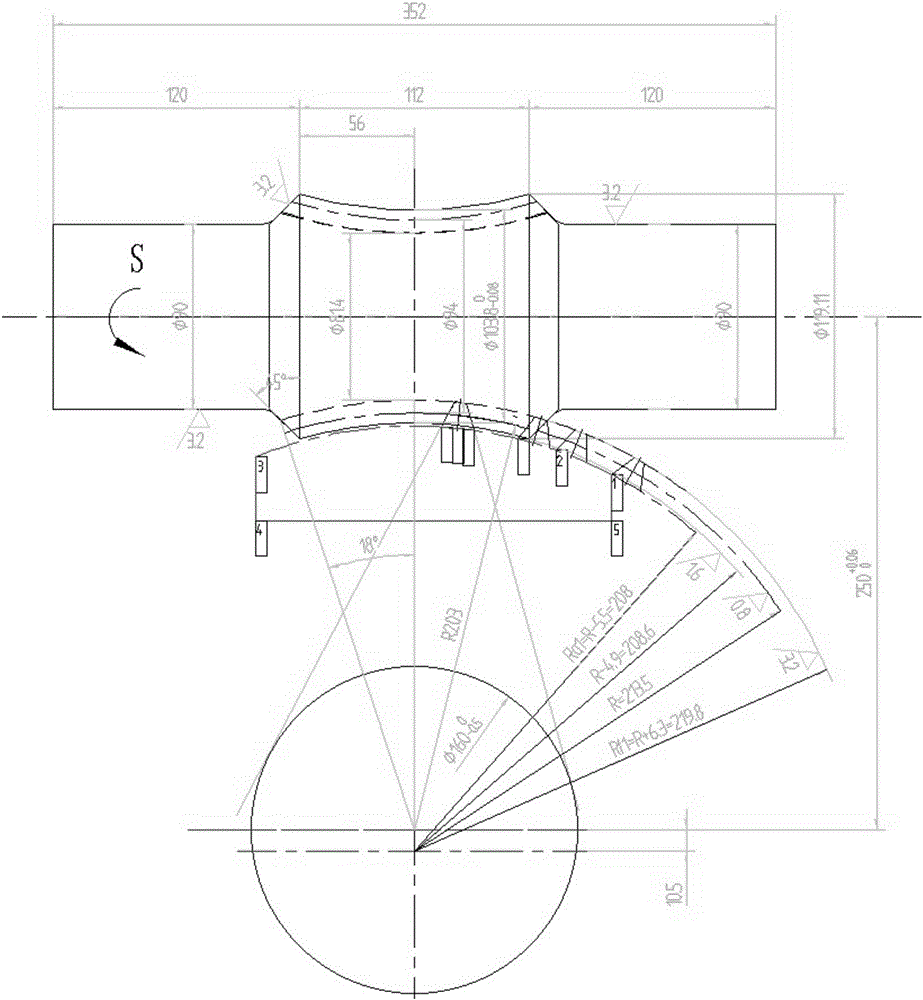
[0048] Example 1: The standard center distance of the worm is 250, the added amount of the center distance is 10.5, the number of worm heads is 2, the arc radius of the worm tooth root Rf1=219.8, the arc radius of the worm tooth top Ra1=208.6, the length of the working part of the worm is 112, and the matching standard The number of worm gear teeth is 58, the radius of the worm gear index circle is 203, the radius of the base circle is 80, the axial tooth thickness of the worm index circle is 10.38, and the right-handed plane quadratic enveloping toroidal worm with a grinding allowance of 0.3 is taken as an example.

[0049] Preparation:

[0050] [1] Measured by CAD drawing, the minimum width of the alveolar bottom is 5.90, and the maximum depth of the alveolar is 11.50. A cemented carbide cutting knife with a main cutting edge width of 5 and a maximum cutting depth of 22 is selected.

[0051] [2] The modification angle of the clamping surface of the cutter body is selected a...


PUM


Abstract

The invention relates to the technical field of turning methods, in particular to a method for processing a helical surface of a toroidal worm by a numerically controlled lathe. The method comprises the following steps of: clamping a to-be-processed worn on the numerically controlled lathe, wherein the plane where the to-be-processed worm is located is S, n and n1 are separately two instantaneous positions, generated when a toothed slot changes as the toroidal worm rotate, of a point on the side surface of a toothed slot in the axial section extending section; moving the tool nose on the corresponding surface of a cut-off tool to the point n, performing bootstrap program for enabling the corresponding tool nose to move to the point n1, carrying out interpolation motion by taking R+m as a cutting radius from the point n1, processing out a circular-arc helical line of one side surface, withdrawing the tool to the initial point n, and cutting a circular-arc helical line of the other side surface in the similar way, thereby completing cutting of the helical surface of the worm. A to-be-processed initial point is determined by performing the bootstrap program, so that the position of the to-be-processed initial point can be accurately determined, dependence on a special numerical-control machine tool is avoided, technical requirements on an operator worker are reduced, manufacturing cost is reduced, the to-be-processed point can be found once, and processing efficiency is greatly improved.

Description

technical field [0001] The invention relates to a turning method, in particular to a method for machining a helical surface of a toroidal worm with a numerically controlled lathe. Background technique [0002] The traditional processing of the helical surface of the toroidal worm is carried out on a special machine tool transformed from a hobbing machine or a lathe, and then ground. This method belongs to the method of processing the tooth shape of the torus worm with a forming knife, but it must be used when processing worms of different specifications. Configure the corresponding cutter head and turning tool. This method has a long processing cycle and high manufacturing cost. Moreover, the adjustment of the machine tool is complicated and cumbersome. The professional requirements for tool sharpening are high, and the technical requirements for workers are high. The existing "Industry and Technology Forum" Volume 10, Issue 24, 2011, Li Song "Using Macro Programs to Realize...

Claims


Application Information

Patent Timeline
IPC IPC(8): B23F13/00
CPCB23F13/00
Inventor 董新会段晓宾王军强顾景江
Owner SINOSTEEL XIAN MACHINERY
Why Eureka
Try Eureka