
Flat fillet welding trolley welding auxiliary device

An auxiliary device, flat fillet welding technology, applied in the direction of auxiliary devices, welding/cutting auxiliary equipment, welding equipment, etc., can solve the problem that the flat fillet welding trolley cannot be used to stop the collision, limit the promotion and use of more than one person, and cannot complete the weld seam welding and other issues to achieve the effect of increasing the quantity, avoiding secondary welding, and reducing labor costs

Active Publication Date: 2017-10-24
QINGDAO BEIHAI SHIPBUILDING HEAVY IND CO LTD
View PDF7 Cites 0 Cited by
  • Summary
  • Abstract
  • Description
  • Claims
  • Application Information

AI Technical Summary

Problems solved by technology

In actual use, if one person manages two or more flat fillet welding trolleys for operation, the effect will be more obvious, but affected by the length of the weld and the functions that can be realized by flat fillet welding trolleys, the promotion of one person with more than one trolley is limited. use
[0003] The currently used flat fillet welding trolley can automatically stop walking when the induction stop switch installed on the side of the flat fillet welding trolley touches the front component during walking. If the control line of the flat fillet welding trolley is connected to the welding machine, the flat fillet welding trolley can be realized. Stop walking, and the welding torch of the welding machine stops welding operations. However, in the process of manufacturing ship components, there are a large number of straight welds. When dealing with such welds, the function of stopping the collision of the flat fillet welding trolley cannot be used, which reduces the production efficiency
At the same time, due to the size of the flat fillet welding trolley itself, the entire weld seam cannot be welded when it is stopped by the function of collision stop

Method used


Image

  • Flat fillet welding trolley welding auxiliary device
  • Flat fillet welding trolley welding auxiliary device
  • Flat fillet welding trolley welding auxiliary device

Examples


Embodiment Construction

[0026] The present invention will be further described in detail below in conjunction with the accompanying drawings and specific embodiments, but the present invention is not limited to these embodiments.

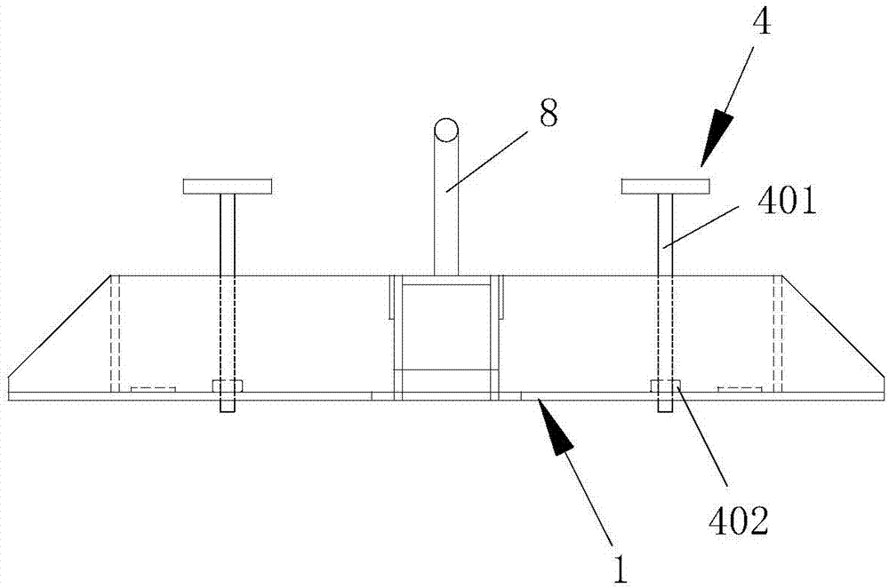
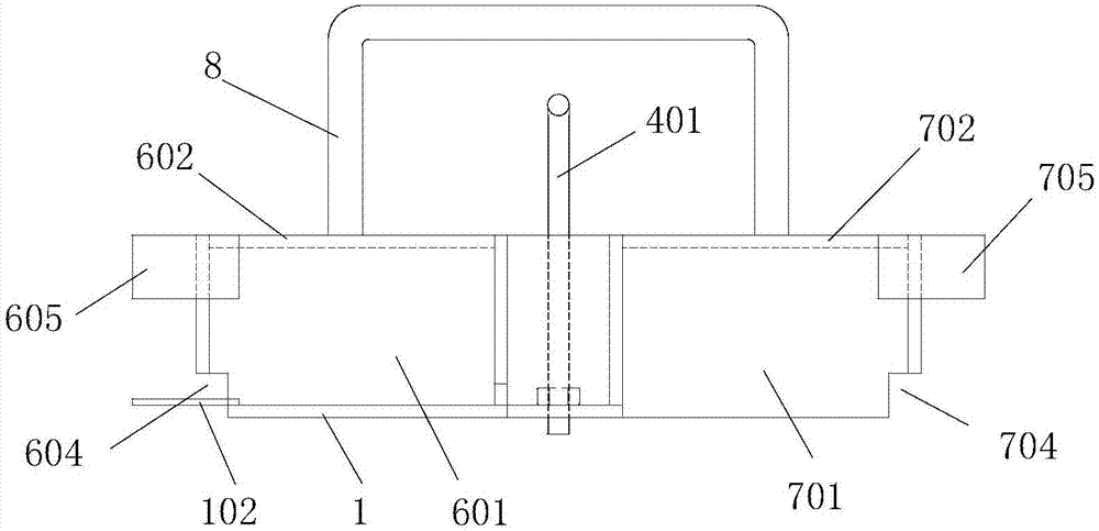
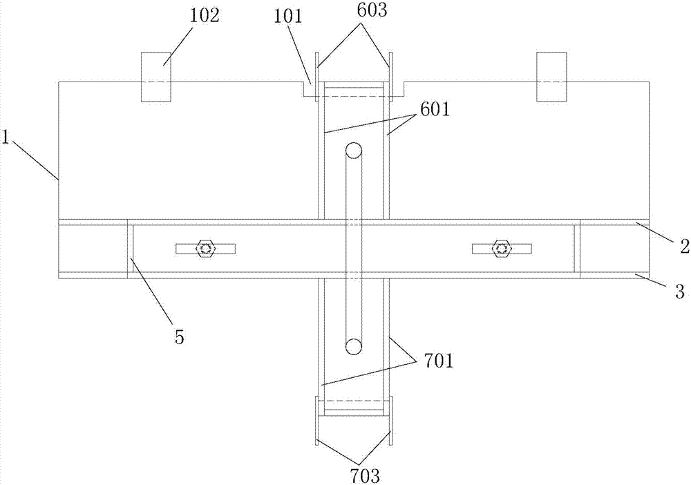
[0027] Such as Figure 1 to Figure 3 As shown, the welding auxiliary device of the flat fillet welding trolley includes a bottom plate 1, a collision plate and a U-shaped plate arranged on one side of the collision plate and connected to the collision plate. A second inner groove 101 is formed on the side of the bottom plate 1 that is in contact with the tire plate 10 of the steel plate to be welded. The arrangement of the second inner groove 101 forms a disconnection between the tire plate 10 and the bottom plate 1 , preventing welding fusion between the tire plate 10 and the bottom plate 1 during the welding process. Two second transition blocks 102 are provided on the side of the bottom plate 1 in contact with the tire plate 10 of the steel plate to be welded, which ar...


PUM


Abstract

The invention discloses a flat fillet welding trolley welding auxiliary device, which comprises a collision plate and a U-shaped plate arranged on one side of the collision plate and connected with the collision plate. The U-shaped plate includes two guide plates parallel to each other and a The top plate of the guide plate, the spacing between the two guide plates is greater than the width of the vertical plate of the steel plate to be welded. The ends of the guide plates not connected with the collision plate are all provided with extension baffles, the extension baffles and the guide plates are parallel to each other, and the ends of each guide plate not connected with the collision plate are also provided with first transition blocks. The invention can extend the running length of flat fillet welding trolleys, realize one-time welding forming of the whole straight weld seam, increase the number of flat fillet welding trolleys supervised by a single person, and improve production efficiency.

Description

technical field [0001] The invention belongs to the technical field of shipbuilding equipment, and in particular relates to a flat fillet welding trolley welding auxiliary device. Background technique [0002] In modern shipbuilding enterprises, there is an assembly line shipbuilding, and welding operations are carried out in different areas and channels according to the small, medium and large assembly and the type of components. Especially in the stage of small assembly, flat fillet welding trolleys are widely used. The use of flat fillet welding trolleys instead of manual welding can not only greatly reduce the labor intensity of workers, but also improve efficiency, reduce the consumption of welding materials, reduce welding grinding, and improve the appearance of welds. Therefore, the use of flat fillet welding trolleys is favored by various shipping companies. favor. In actual use, if one person manages two or more flat fillet welding trolleys for operation, the effec...

Claims


Application Information

Patent Timeline
Patent Type & Authority Patents(China)
IPC IPC(8): B23K37/02B23K37/00
CPCB23K37/00B23K37/0211B23K37/0252
Inventor 张玉明潘宝石孟庆磊
Owner QINGDAO BEIHAI SHIPBUILDING HEAVY IND CO LTD
Learn More