A cervical spine joint assembly for simulating an intelligent robot

An intelligent robot and cervical spine technology, applied in the field of robotics, can solve the problems of low simulation degree, small volume simulation degree, complex structure, etc., and achieve the effect of light weight, high simulation degree, compact and simple structure

Active Publication Date: 2018-05-25
河南豫科电气有限公司
View PDF6 Cites 0 Cited by
  • Summary
  • Abstract
  • Description
  • Claims
  • Application Information

AI Technical Summary

Problems solved by technology

[0003] The purpose of the present invention is to overcome the relatively large volume, complex structure, and low degree of simulation of the existing robotic cervical spine joints, and to provide a cervical spine joint that borrows from the mandibular joint base of the skull and mouth. Cervical spine joint assembly of a simulated intelligent robot with integrated design of mandibular joint, small size and high simulation degree

Method used


Image

  • A cervical spine joint assembly for simulating an intelligent robot
  • A cervical spine joint assembly for simulating an intelligent robot
  • A cervical spine joint assembly for simulating an intelligent robot

Examples


Embodiment Construction

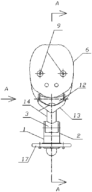
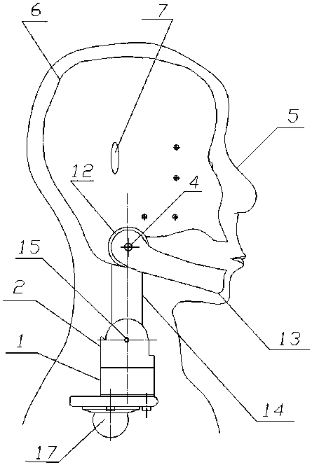
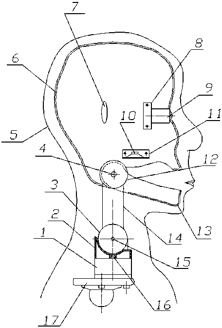
[0015] As can be seen clearly from each figure of specific embodiment, the present invention comprises cervical spine turning neck motor 1, turning neck fork 2, nodding motor 3, skull shell 6, lower jaw 13 and lower jaw motor 12 and forms, wherein nodding motor 3 shells and The lower jaw motor 12 shell and the cervical vertebra rod 14 are an integrated structure, the skull shell 6 is positioned on the shell of the lower jaw motor 12, the lower jaw 13 is positioned on the extension shaft 4 at both ends of the lower jaw motor, and the structural parts of the nodding motor 3 and above are like the skull. The shell 6, the lower jaw 13, the lower jaw motor 12, the cervical vertebra rod 14, etc. are positioned on the neck-rotating fork 2 through the nodding motor output shaft 15, and the neck-rotating fork 2 is positioned on the output shaft 16 of the neck-rotating motor. The entire cervical spine joint assembly is positioned on the On the top vertebra 17 of the vertebral joint assem...


PUM


Abstract

The invention particularly relates to a cervical vertebra joint assembly of a simulation intelligent robot. The cervical vertebra joint assembly is characterized in that the whole cervical vertebra joint assembly comprises a cervical vertebra neck rotating motor, a neck rotating fork, a nodding motor, a head shell, a lower jaw and a lower jaw motor; a nodding motor shell, a lower jaw motor shell and a cervical vertebra rod are of an integrated structure, the head shell is positioned on the lower jaw motor shell, the lower jaw is positioned on output shafts at the two ends of the lower jaw motor, the nodding motor and structural parts such as the head shell, the lower jaw, the lower jaw motor and the cervical vertebra rod on the nodding motor are located on the neck rotating fork through output shafts on the centers at the two ends of the nodding motor, the neck rotating fork is positioned on an output shaft of the neck rotating motor, and the whole cervical vertebra joint assembly is positioned on a top vertebra of the vertebral column joint assembly. The cervical vertebra joint assembly is compact and simple in structure, high in simulation degree, low in weight and high in integration degree.

Description

technical field [0001] The invention relates to the field of robots, in particular to a cervical spine joint assembly for simulating an intelligent robot. Background technique [0002] In the field of robotics in the prior art, there are many structures related to cervical joints. However, most of them use steering gears for cervical spine joints. Since the cervical spine of a real person has two degrees of freedom and the space size is limited, it is more difficult to use steering gears to make a simulated human cervical spine. The existing steering gears are independent of each other. To make two The steering gears form a cervical joint with each other, and the steering gears must be connected to each other through intermediate transition pieces. This makes the cervical spine joints complex and bulky, unable to correspond to the size of real joints, and heavy. Even in some foreign countries with leading robot technology, the cervical joints of their robots are relatively...

Claims


Application Information

Patent Timeline
Patent Type & Authority Patents(China)
IPC IPC(8): B25J17/00B25J9/08B25J9/12
CPCB25J9/08B25J9/12B25J17/00
Inventor 李德福
Owner 河南豫科电气有限公司
Why Eureka
Try Eureka