In-mould cutter pressure-retreating-resistant water gap automatic cutting device

An automatic cutting device and in-mold cutting technology, applied in the field of injection molds, can solve the problems of low production pass rate, incomplete nozzle removal, affecting appearance, etc., and achieve the effect of high pass rate, improved production efficiency, and high degree of automation.

Active Publication Date: 2017-01-04
中山市登盈精密注塑有限公司
View PDF11 Cites 4 Cited by
  • Summary
  • Abstract
  • Description
  • Claims
  • Application Information

AI Technical Summary

Problems solved by technology

[0007] In order to solve the problem in the prior art that under the influence of the injection molding pressure, the cutting knife retreats, resulting in incomplete removal of the nozzle of the product, a low pass rate of the produced piece, and affecting the appearance. The device ensures that the movement of the cutter is locked while the cutter cuts the nozzle, effectively preventing the cutter from retreating under the influence of injection pressure, ensuring the appearance of the product and improving production efficiency

Method used


Image

  • In-mould cutter pressure-retreating-resistant water gap automatic cutting device
  • In-mould cutter pressure-retreating-resistant water gap automatic cutting device
  • In-mould cutter pressure-retreating-resistant water gap automatic cutting device

Examples


Embodiment Construction

[0037] In order to make the technical problems, technical solutions and beneficial effects solved by the present invention clearer, the present invention will be further described in detail below in conjunction with the accompanying drawings and embodiments. It should be understood that the specific embodiments described here are only used to explain the present invention, not to limit the present invention.

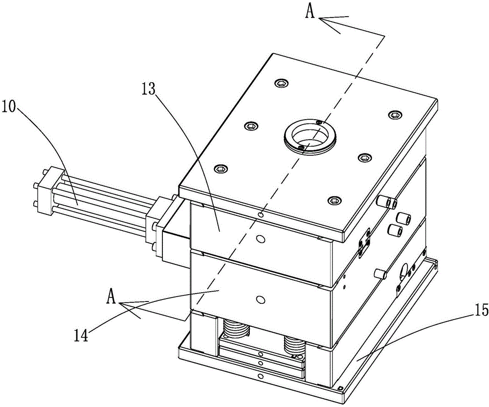
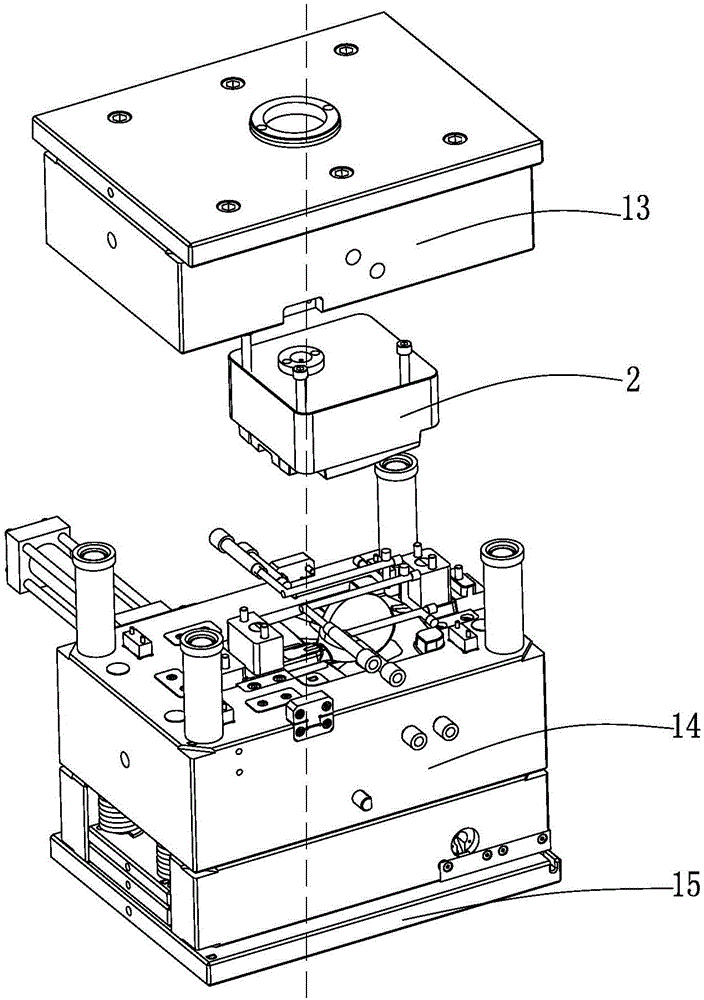
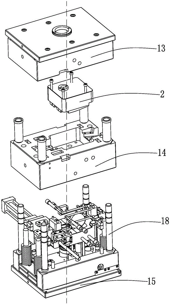
[0038] Such as Figure 1 to Figure 11 As shown, the automatic cutting device for the in-mold cutter anti-pressure water outlet, including the male mold core 1 and the female mold core 2 that cooperates with the male mold core 1 to cover and close, the male mold core 1 and the female mold core 2 cooperate with the cover to form A mold cavity 3 for product molding, the male mold core 1 is provided with a nozzle 4 communicating with the mold cavity 3, and the side of the nozzle 4 communicating with the mold cavity 3 is provided with a nozzle that can extend into the mold ca...


PUM


Abstract

The embodiment of the invention provides an in-mould cutter pressure-retreating-resistant water gap automatic cutting device. The device comprises a male mould core and a female mould core matched with the male mould core in a covering mode. The male mould core and the female mould core are matched and cover each other to form a mould cavity used for product forming, the male mould core is provided with a water gap communicated with the mould cavity, a cutter and a driving locking device are arranged on the side, communicated with the mould cavity, of the water gap, the cutter can extend into the mould cavity to cut the water gap, and the driving locking device drives the cutter to reciprocate and locks the cutter during injection molding to prevent the cutter from retreating under influence of injection molding pressure. The driving locking device locks moving of the cutter and achieves automatic cutting of the cutter, the automation degree is high, the problem that the cutter retreats under the influence of injection molding pressure is effectively prevented, product appearance is guaranteed, and production efficiency is improved.

Description

[0001] Technical field: [0002] The invention relates to the field of injection molds, in particular to an automatic cutting device for an in-mold cutter to prevent pressure and drain outlet. [0003] Background technique: [0004] Most of the plastics nowadays are made by injection molding. During the injection molding process, it is necessary to set up a plastic inlet on the mold. The plastic inlet is connected to the mold cavity and is used to inject molten plastic material into the mold cavity. The molten plastic material enters the mold cavity. The cavity forms the product, and the inlet of the molten plastic material on the product is the nozzle. In order to ensure the efficiency of injection molding and save production costs, generally multiple cavities are designed on the injection mold, and multiple plastic inlets are used. This is Make the injection molding product have a nozzle on the plastic part after injection molding. After the product is formed, the mold needs ...

Claims


Application Information

Patent Timeline
Patent Type & Authority Applications(China)
IPC IPC(8): B29C45/38B29C45/26
CPCB29C45/0025B29C45/2602B29C45/38B29C2045/384
Inventor 朱成恩
Owner 中山市登盈精密注塑有限公司
Why Eureka
Try Eureka