Electrolytic furnace

A technology of electrolytic furnace and hearth, which is applied in the direction of cells, etc., can solve the problems of hindering normal production, lower input power, lower production capacity, etc., and achieve the effect of uniform quality of metal products, large production capacity and short residence time

Active Publication Date: 2017-01-04
GANZHOU KELI RARE EARTH NEW MATERIAL CO LTD
View PDF9 Cites 7 Cited by
  • Summary
  • Abstract
  • Description
  • Claims
  • Application Information

AI Technical Summary

Problems solved by technology

In this technical solution, since the working area of ​​the cathode is larger than the working area of ​​the anode, and the current density of the cathode is smaller than the current density of the anode, the input power decreases and the production capacity decreases; there is a gap between the diversion...

Method used


Image

  • Electrolytic furnace
  • Electrolytic furnace
  • Electrolytic furnace

Examples


Embodiment 1

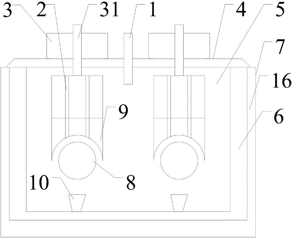
[0038] electrolytic furnace (see figure 1 , Figure 5 and Figure 9 ), including feed pipe 1, exhaust hole 2, anode adjustment part 3, furnace cover 4, furnace chamber 5, furnace wall 6, shell 7, cathode 8, anode 9, crucible 10, insulation layer 16, guide ring 19 and Waterproof insulation part 20. From the outside to the inside are the shell 7, the insulation layer 16, the furnace wall 6, and the furnace 5. The cavity in the furnace wall 6 forms the furnace 5 with an open top. From top to bottom are the anode adjustment part 3 , the furnace cover 4 , the furnace 5 , the anode 9 , the cathode 8 and the crucible 10 . The furnace cover 4 is covered above the opening of the furnace 5 . The number of the anode adjustment part 3, the anode 9, the cathode 8 and the crucible 10 is 1 each, and the cross section of the cathode 8 is circular, located in the furnace 5, and the two ends pass through the furnace wall 6, the insulation layer 16 and the shell respectively. 7 protrudes ou...

Embodiment 2

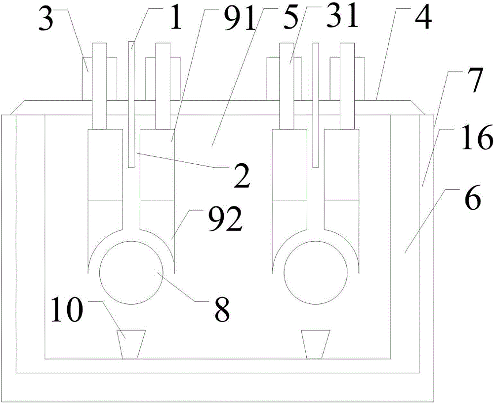
[0044] electrolytic furnace (see figure 1 , Figure 5 and Figure 9 ). This embodiment is basically the same as Embodiment 1, except that the number of the anode adjustment part 3, the anode 9, the cathode 8, the crucible 10, the guide ring 19 and the guide rod 31 is 2 pieces each, and the anode 9, the cathode 8 and the crucible 10 are arranged in parallel in the furnace 5 in pairs. Each of the cathodes 8 is inclined at 3° relative to the horizontal plane along the length direction. The two pieces of crucibles 10 are communicated with each other and come out of the furnace together. Each cathode 8 is inclined relative to the horizontal plane along the length direction so that the product leaves the electrolysis reaction area faster, which is beneficial to concentration and collection.

[0045] Compared with Embodiment 1, this embodiment improves the utilization rate of the furnace 5 and has a large production capacity, which is conducive to the enlargement of the electrol...

Embodiment 3

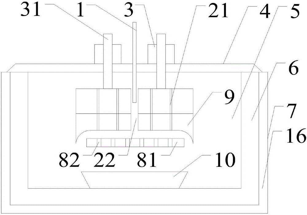
[0047] electrolytic furnace (see figure 2 , Image 6 , Figure 7 , Figure 10 , Figure 11 and Figure 12 ), including feed pipe 1, exhaust channel 2, anode adjustment part 3, furnace cover 4, furnace chamber 5, furnace wall 6, shell 7, cathode 8, anode, crucible 10, insulation layer 16, guide ring 19 and anti Insulation part 20. From the outside to the inside are the shell 7, the insulation layer 16, the furnace wall 6, and the furnace 5. The cavity in the furnace wall 6 forms the furnace 5 with an open top. From top to bottom are the anode adjustment part 3 , the furnace cover 4 , the furnace 5 , the anode, the cathode 8 and the crucible 10 . The furnace cover 4 is covered above the opening of the furnace 5 . There are two anode adjustment components 3, and one anode, one cathode 8 and one crucible 10 each. Described cathode 8 is circular in cross section, is located in furnace 5, and one end passes through furnace wall 6, insulation layer 16 and casing 7 and stretc...


PUM


Abstract

The invention discloses an electrolytic furnace. The electrolytic furnace comprises a shell (7), a heat preservation layer (16), a furnace wall (6) and a hearth (5) from outside to inside. The hearth (5) with an opening in the top is formed in a cavity in the furnace wall (6); an anode adjusting component (3), the heath (5), an anode (9) and a cathode (8) are arranged from top to bottom; the cathode (8) is located in the hearth (5), and at least one end penetrates the furnace wall (6), the heat preservation layer (16) and the shell (7) and stretches out of the shell (7); the anode (9) stretches into the hearth (5) from the top of the hearth (5), and an electrolytic work pair is formed by the anode (9) and the cathode (8); the anode adjusting component (3) controls the anode (9) to move; and the anode (9) is provided with an exhaust channel (2). The electrolytic furnace has the beneficial effects that during electrolytic operation, generated gas can be conveniently escaped, anode uniform consumption and electrolytic technology parameter control is convenient, discharging is convenient, the anode utilization rate is high, the staying time of products in the electrolytic reaction area is short, the yield is high, and the product quality is more uniform.

Description

technical field [0001] The invention relates to an electrolytic furnace for producing rare earth metals and their alloys, an electrolytic furnace group composed of the electrolytic furnace and a use method. The invention belongs to the technical field of rare earth metallurgy equipment and application. Background technique [0002] In the production of rare earth metals and their alloys, electrolysis is a common production method. The electrolysis temperature for the production of rare earth metals and their alloys is usually above about 900°C. [0003] The publication date is August 18, 2010, and the publication number is CN101805914A. The Chinese patent application titled "Bottom Cathode Diversion Type Rare Earth Electrolyzer" discloses "A Bottom Cathode Diversion Type Rare Earth Electrolyzer, Suitable for Rare Earth Electrolyzers Transformation and development. The cathode is placed directly below the anode of the present invention, the bottom of the anode is an arc-sha...

Claims


Application Information

Patent Timeline
IPC IPC(8): C25C3/34C25C7/00
CPCC25C3/34C25C7/00
Inventor 龚斌章立志刘明彪陈炎鑫谢楠林伟清郭雪锋李孝璋江南
Owner GANZHOU KELI RARE EARTH NEW MATERIAL CO LTD
Why Eureka
Try Eureka