
Method for changing airfoil distribution of blade trailing edge side, blade, fan and method for manufacturing blade

A blade trailing edge and airfoil technology, which is applied in the field of deformable devices at the trailing edge of large wind turbine blades, can solve problems such as poor stall performance and stall, and achieve the effects of weakening strength, slowing down load, and improving loading conditions

Inactive Publication Date: 2017-01-04
AVIC HUITENG WINDPOWER EQUIP
View PDF4 Cites 3 Cited by
  • Summary
  • Abstract
  • Description
  • Claims
  • Application Information

AI Technical Summary

Problems solved by technology

[0003] Generally, the blades of large wind turbines use an airfoil with a thickness of 40% near the maximum chord length, and the thickness of the trailing edge of the initially designed airfoil is relatively thin. Compared with the thicker airfoil, this thinner airfoil is prone to stall phenomenon, and its stall performance is also poor

Method used


Image

  • Method for changing airfoil distribution of blade trailing edge side, blade, fan and method for manufacturing blade
  • Method for changing airfoil distribution of blade trailing edge side, blade, fan and method for manufacturing blade
  • Method for changing airfoil distribution of blade trailing edge side, blade, fan and method for manufacturing blade

Examples


Embodiment Construction

[0045] In order to better explain the present invention and facilitate understanding, the present invention will be described in detail below through specific embodiments in conjunction with the accompanying drawings.

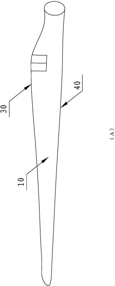
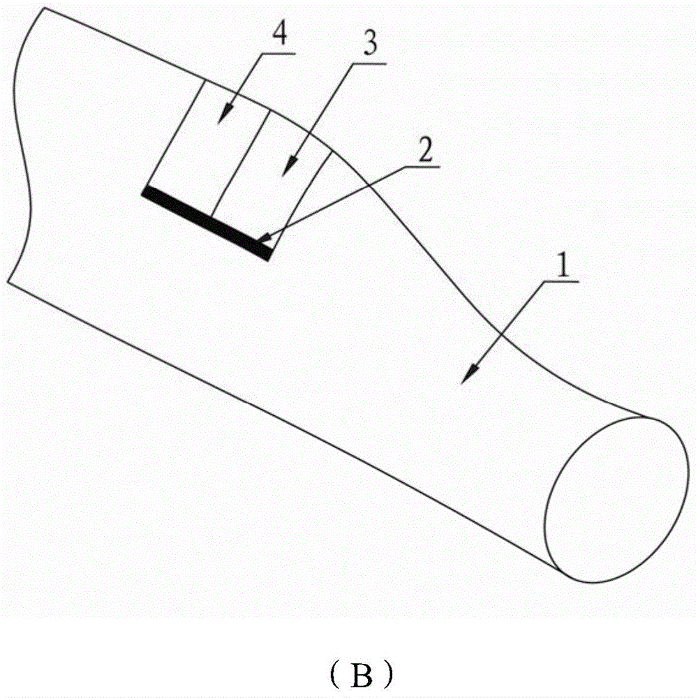
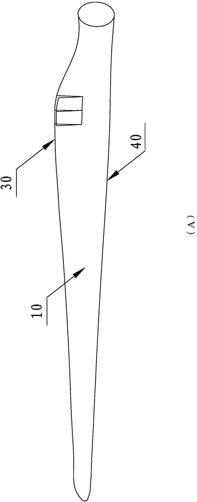
[0046] See Figure 1 to Figure 5 In one embodiment of the present invention, the trailing edge side is provided with a wind turbine blade with a deformable device, which has a blade body 1 , a first fiberboard 3 and a second fiberboard 4 .

[0047] The blade body 1 has a suction surface 10, a position of maximum chord length 20, a leading edge 30 and a trailing edge 40, and the extending direction of the blade root tip is defined as the axial direction X, and the direction extending from the leading edge 30 to the trailing edge 40 is defined as the chord Y direction, the distance between the leading edge 30 and the trailing edge 40 along the chord direction Y is defined as the chord length.

[0048] The predetermined position of the suction surface 10 of the b...


PUM

PropertyMeasurementUnit
lengthaaaaaaaaaa

Abstract

The invention relates to a method for changing airfoil distribution of a blade trailing edge side, a blade, a fan and a method for manufacturing the blade. According to the method, a plurality of fiber boards are stuck near the maximum chord length of a suction surface of the blade, and then the suction surface generates a positive pressure during a normal laminar flow process near the maximum chord length, the fiber boards will not deform, and the power of the blade cannot be affected; and when the incidence angle of a cross section near the maximum chord length is large, the negative pressure is generated, the fiber boards deform, and then the adverse pressure gradient is decreased, and the strength of a harmful eddy is decreased. When the blade trailing edge side generates a harmful eddy, the influence of the eddy on the power and the load can be relieved through automatic deformation, and the blade can operate stably.

Description

technical field [0001] The invention relates to a deformable device for the trailing edge of a large wind turbine blade, which belongs to the application field of new energy technology, and in particular to a method for changing the airfoil distribution on the trailing edge side of the blade, and a deformable device provided on the trailing edge side A wind rotor blade, a fan using the wind rotor blade and a manufacturing method of the wind rotor blade. Background technique [0002] As the length of the blade increases, the speed of the rotor tip increases gradually. When the blade is in normal operation, the angle of attack of the section near the maximum chord length is relatively large. As the angle of attack increases, the front stagnation point moves toward the trailing edge, and the suction peak of the airflow around the front edge increases, making it more difficult for the airflow behind the peak point to flow backward against the reverse pressure gradient, and the ...

Claims


Application Information

Patent Timeline
Patent Type & Authority Applications(China)
IPC IPC(8): F03D11/00B29C70/34
CPCY02P70/50
Inventor 李磊王旭玲陈志强吴映芳
Owner AVIC HUITENG WINDPOWER EQUIP
Learn More