Speed-changing control system, vehicle and gear control method

A technology of a control mechanism and a control method, applied in the field of vehicles, can solve the problems of short service life of the speed change control mechanism and the like

Active Publication Date: 2017-01-04
BEIQI FOTON MOTOR CO LTD
View PDF5 Cites 9 Cited by
  • Summary
  • Abstract
  • Description
  • Claims
  • Application Information

AI Technical Summary

Problems solved by technology

[0005] The main purpose of the present invention is to provide a transmission control mechanism, a vehicle and a gear position control method to solve the problem of short service life of the transmission control mechanism in the prior art

Method used


Image

  • Speed-changing control system, vehicle and gear control method
  • Speed-changing control system, vehicle and gear control method
  • Speed-changing control system, vehicle and gear control method

Examples


Embodiment Construction

[0042] It should be noted that, in the case of no conflict, the embodiments in the present application and the features in the embodiments can be combined with each other. The present invention will be described in detail below with reference to the accompanying drawings and examples.

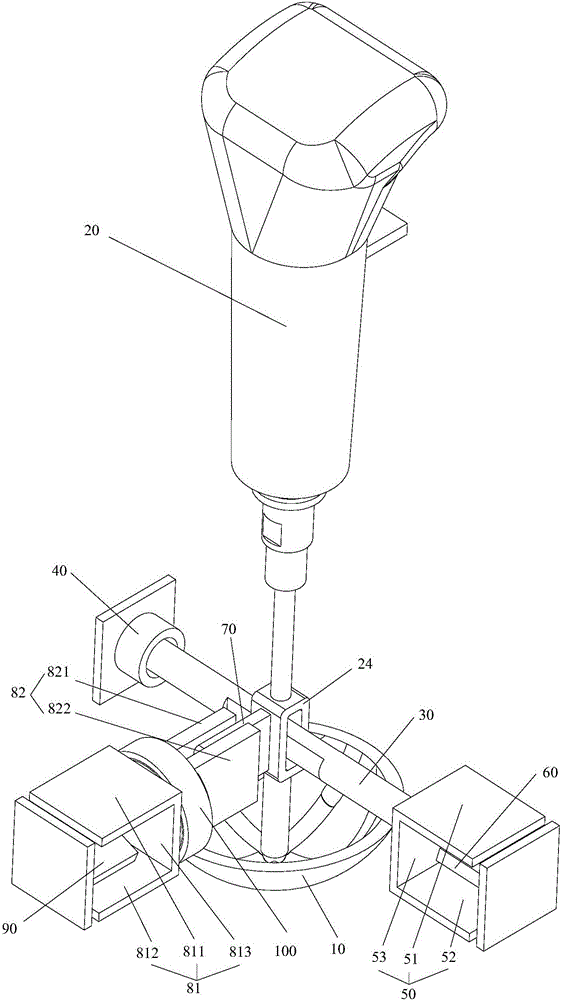
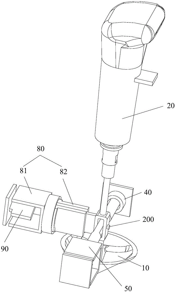
[0043] Such as figure 2 with image 3As shown, the transmission control mechanism of this embodiment includes a chassis 10 , a handle 20 , a first transmission part, a first pole plate part 50 and a first sensor 60 . Wherein, the chassis 10 is fixedly arranged, and the chassis 10 has a slideway, and there are multiple different gear positions on the slideway; the handle 20 has an operating end and a sliding end, and the sliding end is slidably arranged in the slideway, and the handle 20 also has a mounting part 24; the first transmission part is connected with the installation part 24; the first pole plate part 50 is connected with the first transmission part, and the first magnetic field is...


PUM


Abstract

The invention provides a speed-changing control system, a vehicle and a gear control method, wherein the speed-changing control mechanism comprises a chassis, a handle, a first transmission part, a first plate part and a first sensor, wherein the chassis is fixedly arranged, and comprises a slideway; a plurality of different gear positions are arranged on the slideway; the handle comprises an operation end and a sliding end; the sliding end is slidably arranged in the slideway; the handle further comprises a mounting part; the first transmission part is connected with the mounting part; the first plate part is connected with the first transmission part; a first magnetic field is formed in the first plate part; the first sensor is fixedly arranged, extends into the first plate part, and outputs first signals; and when the sliding end slides along the slideway, the mounting part drives the first transmission part to rotate, and the first plate part rotates along with the first transmission part. According to the speed-changing control system, the vehicle and the gear control method, the problem that the service life of the conventional speed-changing control system is short can be solved effectively.

Description

technical field [0001] The present invention relates to the field of vehicles, in particular to a transmission control mechanism, a vehicle and a gear position control method. Background technique [0002] Such as figure 1 As shown, there are currently air-controlled gearboxes and their control systems. The control principle is to install a series of switches at the shifting handle of the body. Every time you change to a different gear position, touch a different switch, and the switch transmits a signal to the controller. , the controller processes the information and controls the corresponding electromagnetic air valve, and finally controls the gear position through the air circuit. The above structure has the following disadvantages: [0003] 1. The air-controlled gearbox and control system use a large number of switches, and the structure is relatively complicated. [0004] 2. Frequent use of the switch will cause high mechanical wear of the switch, resulting in short...

Claims


Application Information

Patent Timeline
Patent Type & Authority Applications(China)
IPC IPC(8): F16H59/02F16H63/42
CPCF16H59/0278F16H63/42F16H2059/026B60K20/02F16H59/02F16H59/044F16H2061/242F16H61/24F16H2061/243
Inventor 初超刘金宝岳言亮尤汀芹
Owner BEIQI FOTON MOTOR CO LTD
Why Eureka
Try Eureka