
Drive method for mechanical drive device and mechanical drive device

A technology of mechanical drive and drive method, which is applied in transmission control, mechanical equipment, components with teeth, etc., can solve problems such as inconvenience for users, single drive device, and inability to change the working mode of the distributor.

Inactive Publication Date: 2017-01-04
欧体自动化技术(上海)有限公司
View PDF5 Cites 1 Cited by
  • Summary
  • Abstract
  • Description
  • Claims
  • Application Information

AI Technical Summary

Problems solved by technology

[0002] In the current field of pharmaceutical machinery, food machinery and cosmetic machinery, the driving devices are single-function. For example, the filling machine in pharmaceutical machinery is divided into continuous filling machine and intermittent filling machine during equipment manufacturing. The filling machine cannot change the working mode of the filling machine, which brings great inconvenience to users in the use of different raw materials

Method used


Image

  • Drive method for mechanical drive device and mechanical drive device
  • Drive method for mechanical drive device and mechanical drive device
  • Drive method for mechanical drive device and mechanical drive device

Examples


Embodiment 1

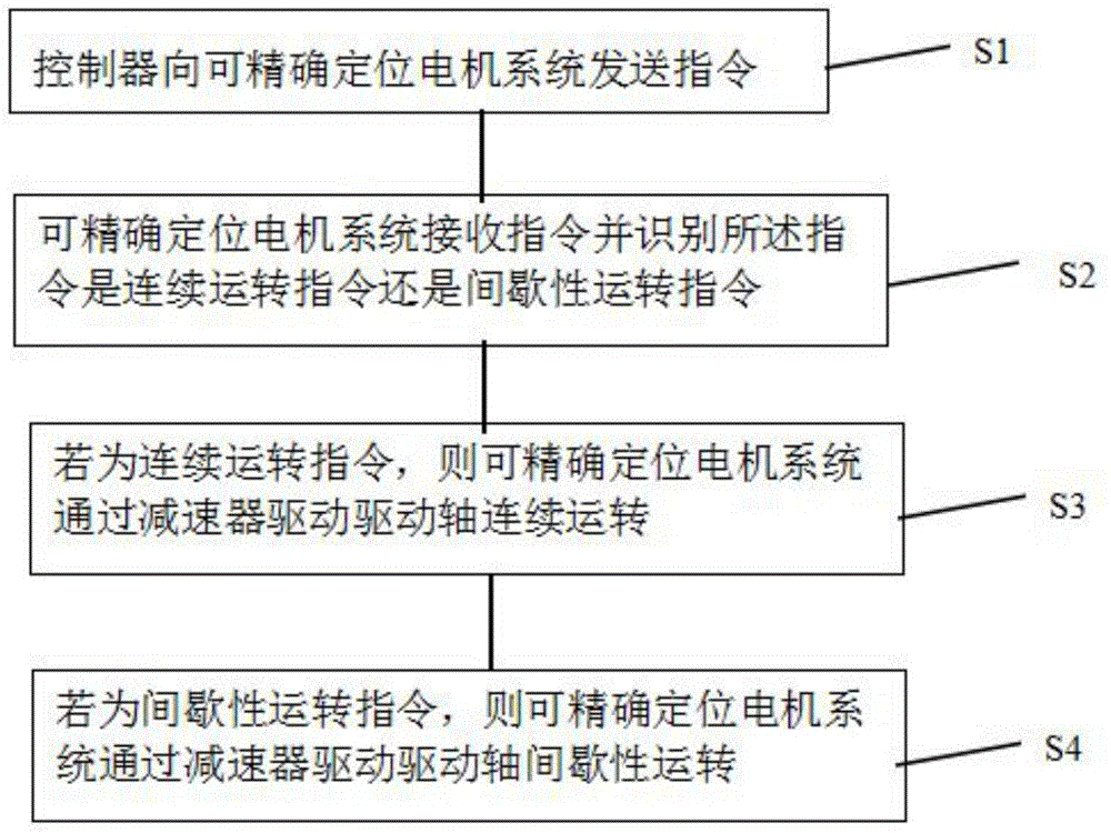
[0042] Embodiment one, such as figure 1 As shown, a driving method for a mechanical driving device, the method includes the following steps,

[0043] Step S1: the controller 11 sends an instruction to the precise positioning motor system 1,

[0044] Firstly, the controller 11 sends instructions to the motor system 1 capable of precise positioning. The motor system 1 capable of precise positioning may adopt servo motors or other motors capable of precise positioning. The motor system 1 capable of precise positioning includes a signal input terminal and a power output terminal. The power input end of the precise positioning motor system 1 is connected to the controller 11, and the power output end of the precise positioning motor system 1 is connected to the reducer 2; Step S2: The precise positioning motor system 1 receives the instruction And identifying whether the instruction is a continuous operation instruction or an intermittent operation instruction, the instruction in ...

Embodiment 2

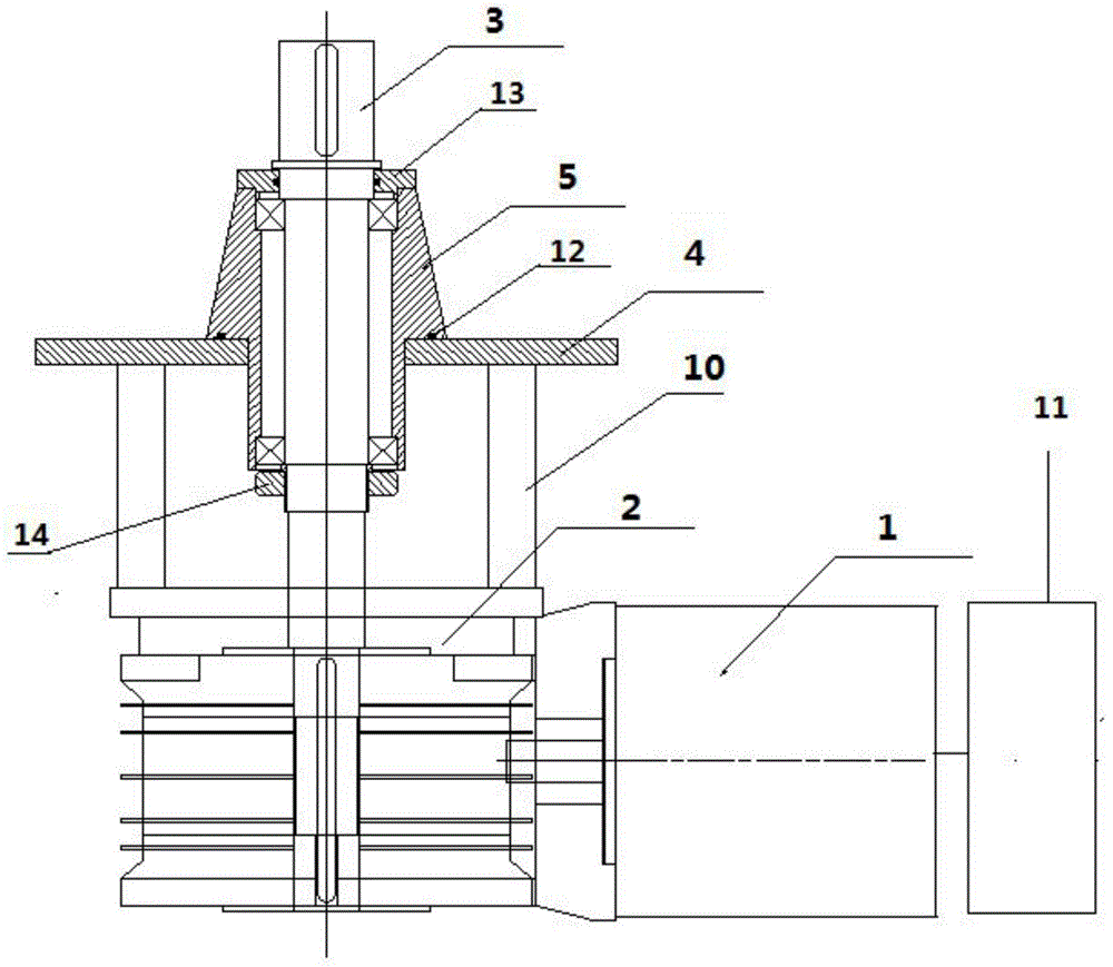
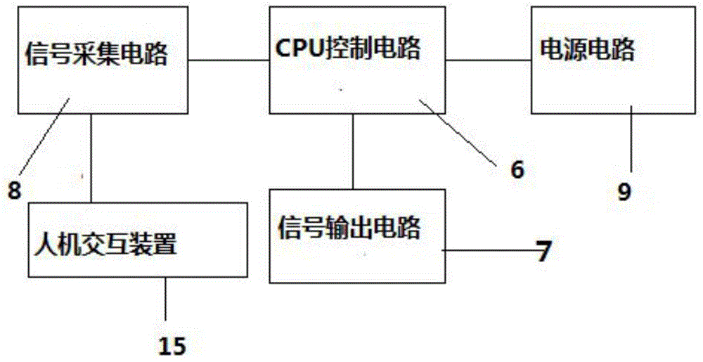
[0047] Embodiment two, such as figure 2 with image 3 As shown, a mechanical drive device includes a precisely positioned motor system 1, a reducer 2, a drive shaft 3 and a controller 11. The precisely positioned motor system 1 includes a signal input end and a power output end. The power output end of the positioning motor system 1 is connected to the reducer 2, the reducer 2 is connected to the drive shaft 3, and the controller 11 is connected to the signal input end of the precise positioning motor system 1, so The controller 11 sends an instruction to the precise positioning motor system 1, and the precise positioning motor system 1 receives the instruction and identifies whether the instruction is a continuous operation instruction or an intermittent operation instruction. If it is a continuous operation instruction, the precise positioning motor system 1 The drive shaft 3 is driven to run continuously through the reducer 2. If it is an intermittent operation command, t...


PUM


Abstract

The invention provides a drive method for a mechanical drive device and the mechanical drive device. The drive method comprises the following steps that a controller sends a command to a motor system capable of realizing accurate positioning; the motor system capable of realizing accurate positioning receives the command and identifies whether the command is a continuous running command or an intermittent running command; if the command is the continuous running command, the motor system capable of realizing accurate positioning drives a drive shaft to continuously run through a reducer; and if the command is the intermittent running command, the motor system capable of realizing accurate positioning drives the drive shaft to intermittently run through the reducer. With adoption of the drive method for the mechanical drive device and the mechanical drive device, the features of intermittent rotation and continuous rotation of a mechanical device can be shared by same equipment, thus intermittent rotation and continuous rotation coexist on one device, and electromechanical integration control is applied to mechanical equipment.

Description

technical field [0001] The invention relates to the field of machinery manufacturing, in particular to a driving device and a driving method for pharmaceutical machinery, food machinery and cosmetic machinery. Background technique [0002] In the current field of pharmaceutical machinery, food machinery and cosmetic machinery, the driving devices are single-function. For example, the filling machine in pharmaceutical machinery is divided into continuous filling machine and intermittent filling machine during equipment manufacturing. The dispensing machine cannot change the working mode of the dispensing machine, which brings great inconvenience to users in the use of different raw materials. Contents of the invention [0003] In view of the above-mentioned deficiencies in the current driving method of the mechanical driving device, the present invention provides a driving method for the mechanical driving device and the driving device, which can realize the free choice of ...

Claims


Application Information

Patent Timeline
Patent Type & Authority Applications(China)
IPC IPC(8): F16H61/02F16H63/02F16H61/00
CPCF16H61/0006F16H61/0202F16H63/02
Inventor 庄育斌
Owner 欧体自动化技术(上海)有限公司
Learn More