Sealing structure for industrial machinery

A technology of sealing structure and industrial machinery, applied in the direction of engine sealing, mechanical equipment, engine components, etc., can solve the problems of poor sealing structure and difficult to meet industrial needs, and achieve the effect of good sealing, simple structure and reasonable design

Inactive Publication Date: 2017-01-04
周末
4 Cites 0 Cited by

AI-Extracted Technical Summary

Problems solved by technology

[0005] Sealing is required in the industrial production process, but the existing...

Abstract

The invention relates to a sealing structure for industrial machinery. The sealing structure comprises a connecting plate, wherein a positioning ring is arranged in the connecting plate; a contact surface between the positioning ring and the connecting plate is of a step shape; the positioning ring is in contact with a lower friction plate; the lower friction plate is in contact with an upper friction plate; a rotating rod is arranged at the center of the positioning ring; the upper side of the upper friction plate is connected with a moveable ring; the upper side of the moveable ring is in contact with a tensioning spring; and the upper end of the tensioning spring is in contact with a locking nut. The sealing structure for industrial machinery is simple and reasonable in design. According to the invention, the positioning ring, the lower friction plate, the upper friction plate and the tensioning spring are arranged, so that the mutual tensioning of the positioning ring, the lower friction plate and the upper friction plate can be realized through the tensioning spring, a better sealing property can be achieved and the requirement of industrial production can be met.

Application Domain

Engine seals

Technology Topic

EngineeringLow friction +1

Image

  • Sealing structure for industrial machinery

Examples

  • Experimental program(1)

Example Embodiment

[0014] In order to make the objectives, technical solutions and advantages of the present invention clearer, the present invention will be further described in detail below with reference to the accompanying drawings and embodiments. It should be understood that the specific embodiments described herein are only used to explain the present invention, but not to limit the present invention.
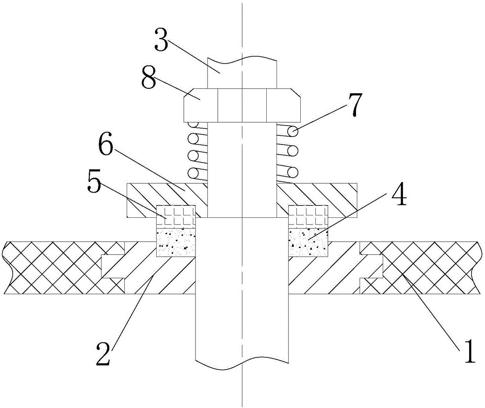
[0015] see figure 1 , figure 1 It is a schematic diagram of the structure of the present invention.
[0016] An industrial mechanical seal structure includes a connecting plate 1, a positioning ring 2 is arranged inside the connecting plate 1, the contact surface between the positioning ring 2 and the connecting plate 1 is stepped, and the positioning ring 2 and the lower friction The plates 4 are in contact, and the lower friction plate 4 is in contact with the upper friction plate 5 , wherein the lower friction plate 4 and the upper friction plate 5 have the same diameter. The central position of the positioning ring 2 is provided with a rotating rod 3, the upper side of the upper friction plate 5 is connected with the moving ring 6, wherein the upper friction plate 5 is embedded in the moving ring 6, and the rotating rod 3 is connected with the moving ring 6. The locking nuts 8 are connected by threads, the upper side of the moving ring 6 is in contact with the tensioning spring 7 , and the upper end of the tensioning spring 7 is in contact with the locking nut 8 . When the present invention is in use, the positioning ring 2, the lower friction plate 4 and the upper friction plate 5 can be mutually tensioned by the tensioning spring 7, so as to achieve better sealing and meet the needs of industrial production.
[0017] In the description of the present invention, unless otherwise expressly specified and limited, the terms "installed", "connected", "connected" and "fixed" should be understood in a broad sense, for example, it may be a fixed connection or a detachable connection , or integrated; it can be a mechanical connection or an electrical connection; it can be a direct connection or an indirect connection through an intermediate medium, and it can be the internal connection of the two elements or the interaction relationship between the two elements. For those of ordinary skill in the art, the specific meanings of the above terms in the present invention can be understood in specific situations.
[0018] The above descriptions are only preferred embodiments of the present invention and are not intended to limit the present invention. Any modifications, equivalent replacements and improvements made within the spirit and principles of the present invention shall be included in the protection of the present invention. within the range.

PUM

no PUM

Description & Claims & Application Information

We can also present the details of the Description, Claims and Application information to help users get a comprehensive understanding of the technical details of the patent, such as background art, summary of invention, brief description of drawings, description of embodiments, and other original content. On the other hand, users can also determine the specific scope of protection of the technology through the list of claims; as well as understand the changes in the life cycle of the technology with the presentation of the patent timeline. Login to view more.

Similar technology patents

Body condition measuring device

InactiveUS20050234351A1simple structure
Owner:DENSO CORP

Magnetic cooling apparatus and control method thereof

ActiveUS20130180263A1simple structure
Owner:SAMSUNG ELECTRONICS CO LTD

Dual-Drivetrain of Power-Assist Vehicle

InactiveUS20100181130A1enhance uphill momentumsimple structure
Owner:CHOU WEN CHENG

Classification and recommendation of technical efficacy words

  • Simple structure
  • reasonable design

Sharing system for air-conditioning coat

InactiveCN107440179ASimple structureeasy to wear
Owner:QINGDAO HAIER AIR CONDITIONER GENERAL CORP LTD

Feeding device of sorter of batteries plate

InactiveCN101357717ASimple structurecooperate well
Owner:NANJING NORMAL UNIVERSITY

Emergency parachuting device and method for multiple-rotor unmanned aerial vehicle

InactiveCN103895870Aavoid aircraft crashSimple structure
Owner:SOUTH CHINA AGRI UNIV +1

Method for coal and gas outburst simulation experiment

Owner:CHINA COAL TECH ENG GRP CHONGQING RES INST

Embedding accuracy control construction method for embedded part of overlong equipment foundation platform

InactiveCN102134879Areasonable designSimple construction steps
Owner:SCEGC NO 6 CONSTR ENG GRP CO LTD

Frequency hopping communication anti-interference method based on cognitive radio

ActiveCN103441779AImprove anti-jamming communication abilityreasonable design
Owner:深圳市研谱科技有限公司
Why Eureka
Try Eureka