Anti-frosting heat recovery system for preheating outdoor fresh air

An anti-frost and heat recovery technology, applied in ventilation and heating energy recovery systems, ventilation systems, heating and ventilation control systems, etc. Does not prevent problems such as frosting

Inactive Publication Date: 2017-01-04
GUANGDONG UNIV OF TECH
View PDF6 Cites 9 Cited by
  • Summary
  • Abstract
  • Description
  • Claims
  • Application Information

AI Technical Summary

Problems solved by technology

[0002] The air-air heat recovery system has the advantages of improving indoor air quality and reducing energy consumption as an indoor ventilation device. However, there are still great obstacles in the application of severe cold and cold regions. Due to the low outdoor temperature and high indoor The heat exchange device in the system may have different degrees of frosting problems
If the accumulated frost is not cleared in time, it will block the air heat exchange channel and reduce the heat transfer area, which will significantly increase the air flow resistance and heat exchange heat resistance, resulting in a decline in the overall performance of the air-to-air heat recovery system
[0003] In the current equipment similar to the present invention, most of them use methods such as preheating by external preheater or defrosting by electric heating, but it needs to consume extra energy (electric energy or heat energy) to heat the fresh air, thus reducing the heat recovery device of the whole system. efficiency
[0004] Secondly, due to the lack of effective monitoring of frosting, it is impossible to prevent frosting and can only be defrosted after frosting occurs, which also leads to a decline in the overall performance of the system heat recovery system

Method used


Image

  • Anti-frosting heat recovery system for preheating outdoor fresh air
  • Anti-frosting heat recovery system for preheating outdoor fresh air
  • Anti-frosting heat recovery system for preheating outdoor fresh air

Examples


Embodiment Construction

[0024] The purpose of the present invention is to overcome the consumption of extra energy in the prior art to heat the fresh air, and to use the waste heat of the exhaust air to preheat the fresh air, thereby effectively improving the heat exchange efficiency of the entire system.

[0025] In order to enable those skilled in the art to better understand the technical solutions provided by the present invention, the present invention will be further described in detail below with reference to the accompanying drawings and specific embodiments.

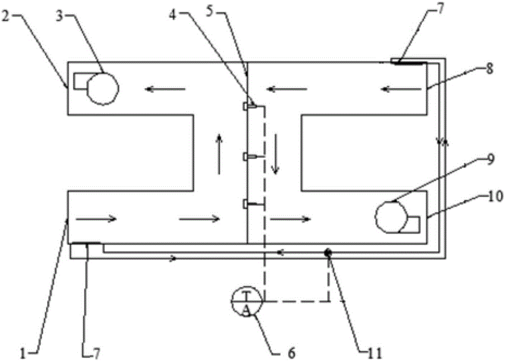
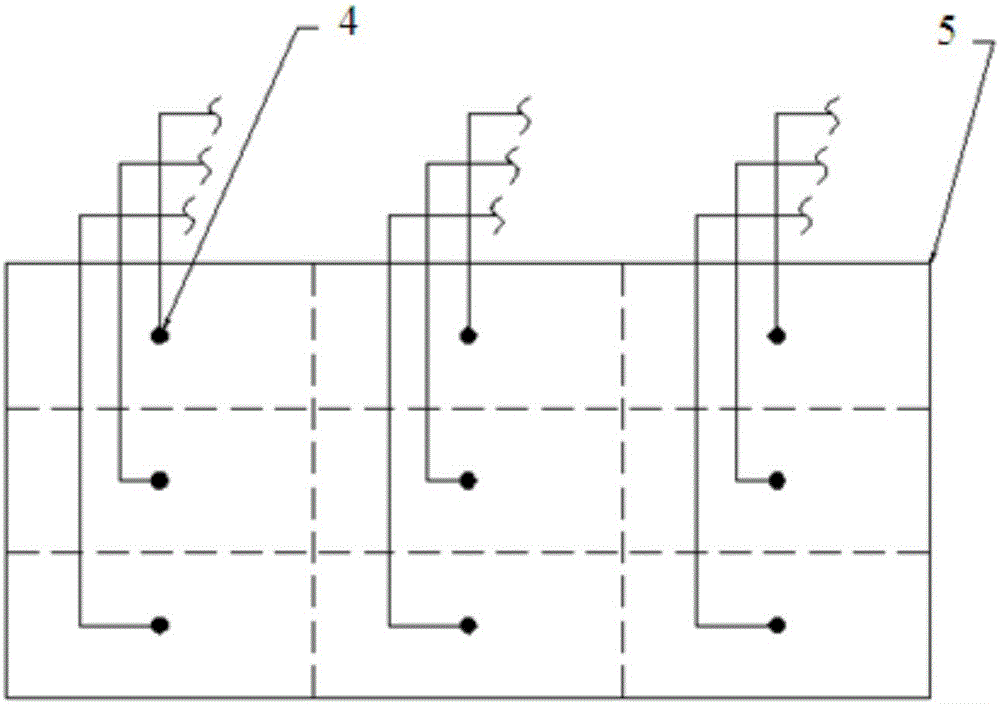
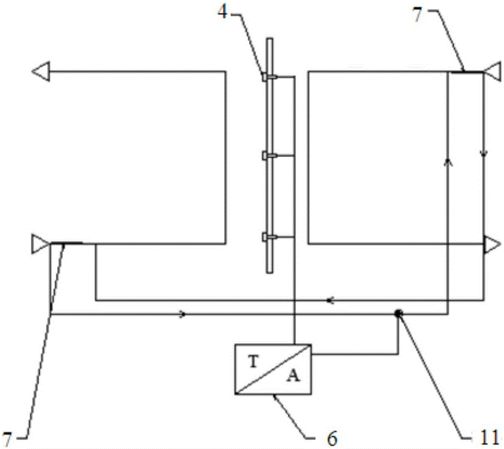
[0026] Please refer to figure 1 , figure 2 , image 3 with Figure 4 , The present invention provides an anti-frosting heat recovery system for preheating outdoor fresh air, which includes a fresh air passage, an exhaust duct, a central heat exchange plate 5 and an anti-frosting system. The fresh air inlet 8 of the fresh air channel is connected with the outdoor fresh air, the exhaust air inlet 1 of the exhaust air channel is connected with...


PUM


Abstract

The invention provides an anti-frosting heat recovery system for preheating outdoor fresh air. The system comprises a fresh air channel, an exhaust air channel, a central heat exchange plate and an anti-frosting system. The outdoor fresh air enters the fresh air channel from a fresh air inlet, indoor exhaust air enters the exhaust air channel from an exhaust air inlet, a circulating pump pushes heat exchange working media in heat exchangers to flow, the temperature of the indoor exhaust air is higher than the temperature of the outdoor fresh air, enhanced heat exchange between the indoor exhaust air and the outdoor fresh air can be realized through the heat exchangers, and therefore the temperature of the central heat exchange plate which the outdoor fresh air makes contact with is raised. The system overcomes the defect that in the prior art, extra energy is consumed to heat fresh air; through a circulating loop formed by the heat exchangers arranged at the exhaust air inlet and the fresh air inlet, heat of the exhaust air is utilized for preheating the fresh air, thus, the problem that an air heat exchange channel frosts due to excessively low outdoor fresh air temperature is solved, and the heat exchange efficiency of the whole system is effectively improved.

Description

Technical field [0001] The invention belongs to the technical field of air anti-frosting, and particularly relates to an anti-frosting heat recovery system for preheating outdoor fresh air. Background technique [0002] As an indoor ventilation device, the air-air heat recovery system has the advantages of improving indoor air quality and reducing energy consumption. However, there are still great obstacles in its application in severe cold and cold areas. Due to the low outdoor temperature and high indoor humidity, heat recovery The heat exchange devices in the system may have different degrees of frosting. If the frost is not cleared in time, it will block the air heat exchange channel and reduce the heat transfer area, which will significantly increase the air flow resistance and heat transfer resistance, resulting in a decline in the overall performance of the air-air heat recovery system. [0003] In the current equipment similar to the present invention, most methods such as...

Claims


Application Information

Patent Timeline
Patent Type & Authority Applications(China)
IPC IPC(8): F24F11/00F24F11/02F24F12/00F24F13/30
CPCF24F12/002F24F13/30
Inventor 宋孟杰陈颖郑晓生廖立元黄文毅罗向龙廉迎战
Owner GUANGDONG UNIV OF TECH
Why Eureka
Try Eureka