
Correction method of radar calibration errors

A technology for calibrating errors and correction methods, applied in radio wave measurement systems, instruments, etc., can solve problems such as large amount of calculation, complex calculation process, and poor real-time performance.

Active Publication Date: 2017-01-04
中国人民解放军防空兵学院
View PDF5 Cites 33 Cited by
  • Summary
  • Abstract
  • Description
  • Claims
  • Application Information

AI Technical Summary

Problems solved by technology

[0011] The purpose of the present invention is to provide a radar calibration error correction method to solve the problems of large amount of calculation, complicated calculation process and poor real-time performance of the radar calibration method in the prior art.

Method used


Image

  • Correction method of radar calibration errors
  • Correction method of radar calibration errors
  • Correction method of radar calibration errors

Examples


Embodiment Construction

[0046] In order to facilitate the understanding of the present invention, the present invention will be described in more detail below in conjunction with the accompanying drawings and specific embodiments. Preferred embodiments of the invention are shown in the accompanying drawings. However, the present invention can be implemented in many different forms and is not limited to the embodiments described in this specification. On the contrary, these embodiments are provided to make the understanding of the disclosure of the present invention more thorough and comprehensive.

[0047] It should be noted that, unless otherwise defined, all technical and scientific terms used in this specification have the same meaning as commonly understood by those skilled in the technical field of the present invention. Terms used in the description of the present invention are only for the purpose of describing specific embodiments, and are not used to limit the present invention. The term "...


PUM


Abstract

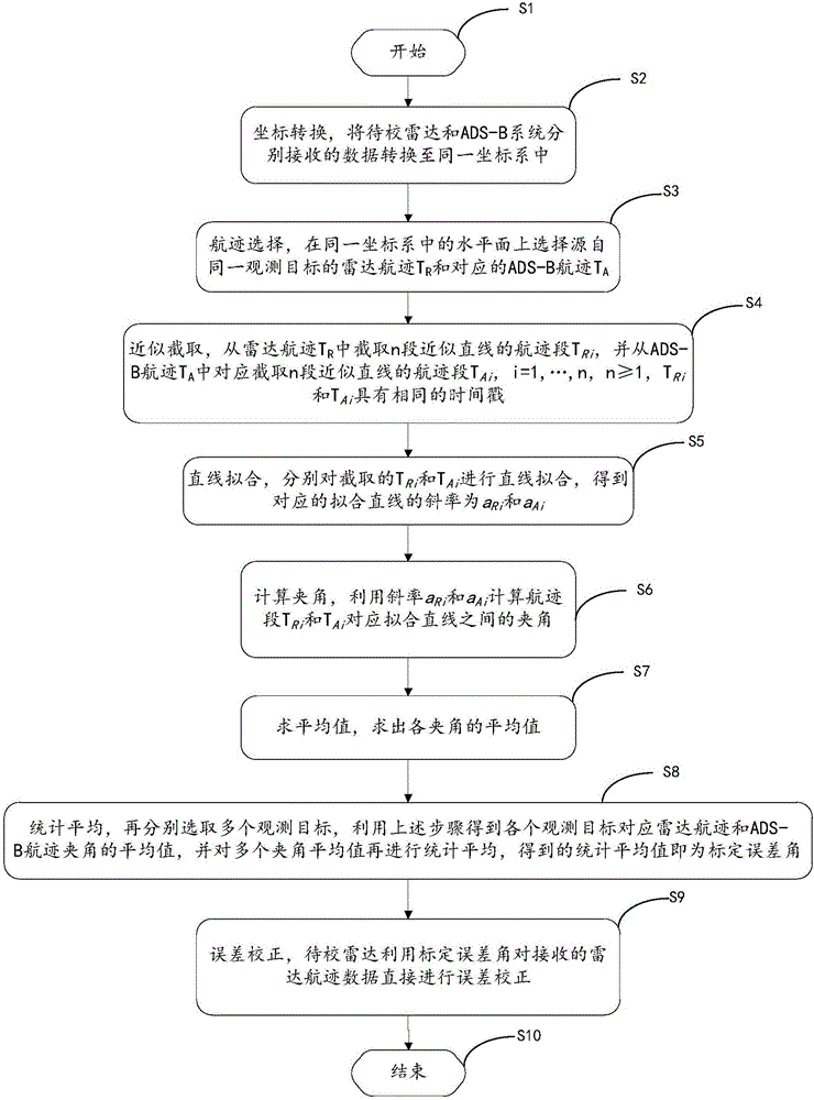
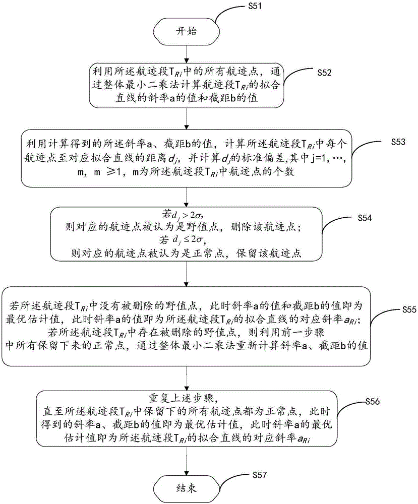
The invention discloses a correction method of radar calibration errors. The correction method comprises steps of: firstly, selecting two tracks from the same observation target from an ADS-B system and a radar situation graph; further selecting multiple track segments approximate to straight lines from the tracks; by use of the whole least square method based on outlier elimination, carrying out straight line fitting on the track segments; eliminating abnormal points in the track segments; solving an included angle between every fitted straight lines of the same track segment of the radar and the ADS-B; solving an average value for included angles of the track segments, thereby obtaining an included angle average value of two tracks of the target; then, selecting multiple observation targets, and solving the corresponding included angle average value of the two tracks by use of the above method; carrying out averaging calculation on all included angle average values, and finally obtaining a calibration error angle of the radar; and by use of the calibration error angle, compensating an azimuth angle measured by the to-be-corrected radar, thereby finishing the correction on the to-be-corrected radar calibration errors. According to the invention, quantitative analysis and proving are performed through measured data, so the correction method is simple in design, convenient to operate and highly practical, has very obvious correction effects on the radar calibration errors and precision degree of tracking a flight target by the radar is greatly increased.

Description

technical field [0001] The invention relates to the field of electronic equipment calibration, in particular to a radar calibration error correction method. Background technique [0002] The calibration error of the radar is mainly composed of the following two errors: one is that when the radar tracks and measures the target, it usually takes the radar optical axis as the reference and the electrical axis to align with the target, but it is difficult to achieve complete accuracy of the radar optical axis and the electrical axis. There is no deviation in coincidence, and the optical axis and the electrical axis will intersect to form a small angle, that is, the error caused by the inconsistency of the photoelectric axis; second, when the radar is used to calibrate the direction, the steering wheel is often used to calibrate the reverse target, but because the steering wheel There is an error in determining the north itself, so using the steering wheel to calibrate the radar ...

Claims


Application Information

Patent Timeline
IPC IPC(8): G01S7/40
CPCG01S7/40
Inventor 李鹏飞王世军万明杰黄沈华纳学柱刘东维张培峰韩金城彭浩朱捷王春新
Owner 中国人民解放军防空兵学院
Learn More