
Object three-dimensional reconstruction method based on single-optical-field camera

A light field camera, 3D reconstruction technology, applied in the field of 3D reconstruction

Inactive Publication Date: 2017-01-04
广州首感光电科技有限公司
View PDF5 Cites 18 Cited by
  • Summary
  • Abstract
  • Description
  • Claims
  • Application Information

AI Technical Summary

Problems solved by technology

[0002] In the prior art, the acquisition technology of the three-dimensional data of the virtual reality of the measured object is scattered in various documents, but each has its own shortcomings

Method used


Image

  • Object three-dimensional reconstruction method based on single-optical-field camera
  • Object three-dimensional reconstruction method based on single-optical-field camera
  • Object three-dimensional reconstruction method based on single-optical-field camera

Examples


Embodiment Construction

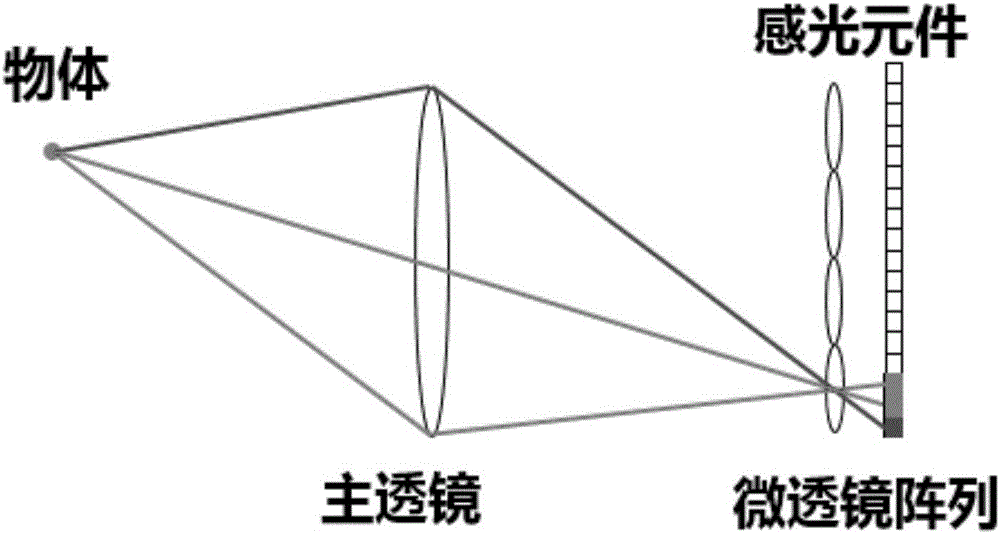
[0046] The three-dimensional reconstruction method of the flow field based on a single light field camera of the present invention obtains the three-dimensional coordinates of the object through a deconvolution algorithm by adding a pre-acquired calibration image and a PSF to a single shot of the object. Contains the following steps:

[0047] 1) Microlens calibration map acquisition and microlens center positioning

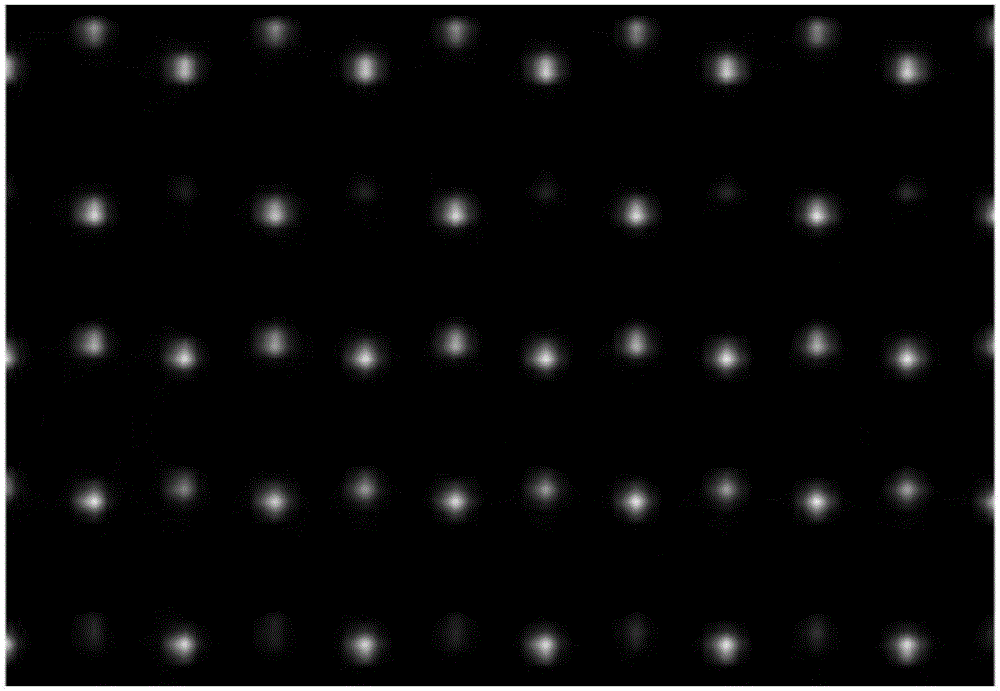
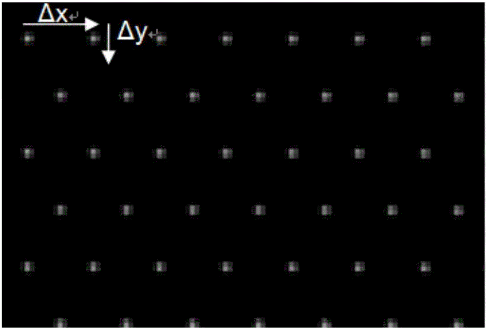
[0048] Due to the needs of the algorithm, the coordinate information of the microlens is used in all post-processing of the light field image, and these coordinates will change over time due to some external factors. Therefore, before taking a set of light field photos, a calibration is required. The method is to place a whiteboard far from the light field camera, adjust the aperture to the minimum, and adjust the exposure time so that the image is not overexposed or underexposed. The photo taken at this time can be seen as consisting of light-emitting points ju...


PUM


Abstract

An object three-dimensional reconstruction method based on a single-optical-field camera comprises the following steps of S101, acquiring a micro-lens calibration graph by means of a single optical field camera, and positioning the center of a micro lens; S102, generating an optical field image of a point spread function (PSF) by means of a simulating manner; S103, acquiring the optical field image of an object by means of the single optical field camera; S104, performing multiple focusing processing on the optical field picture of the object and the optical field image of the PSF, thereby acquiring a three-dimensional optical field image set; S105, performing deconvolution algorithm processing on the three-dimensional optical field image set of the object for acquiring three-dimensional information of the object; and S106, calculating the maximal value of the three-dimensional information on a cross section, using the maximal value as the position of the object, and acquiring the three-dimensional structure of the object.

Description

technical field [0001] The invention belongs to the technical field of three-dimensional reconstruction, and particularly relates to a three-dimensional reconstruction method of a target object based on a single light field camera. Background technique [0002] In the prior art, technologies for acquiring the three-dimensional data of the virtual reality of the measured object are scattered in various documents, but each has its own shortcomings. For example, there are documents: [0003] [1] Hartley R, Ha, Zisserman A, et al. Multi-View Geometry in Computer Vision [M]. Anhui University Press, 2002. [0004] [2]Gonzalez R C,Woods R E.Digital image processing[J].Nueva Jersey,2008. [0005] [3] Levoy M, Hanrahan P. Light field rendering [C] / / Proceedings of the 23rd annual conference on Computer graphics and interactive techniques. ACM, 1996:31-42. SUMMARY OF THE INVENTION [0006] The purpose of the present invention is to provide a three-dimensional reconstruction method...

Claims


Application Information

Patent Timeline
IPC IPC(8): G06T17/00G06T7/60G06T15/00
CPCG06T17/00G06T15/005
Inventor 李思嘉
Owner 广州首感光电科技有限公司
Learn More