System and method for forming low-frequency radio array digital beam

A digital beam and array technology, applied in the field of low-frequency radio array digital beamforming systems, to achieve the effects of improving calculation speed and accuracy, high precision, and avoiding signal attenuation and amplitude/phase inconsistency

Pending Publication Date: 2017-01-04
SHANGHAI ASTRONOMICAL OBSERVATORY CHINESE ACAD OF SCI
View PDF7 Cites 11 Cited by
  • Summary
  • Abstract
  • Description
  • Claims
  • Application Information

AI Technical Summary

Problems solved by technology

Therefore, there is no precedent for using digital beamforming technology to carry out interferometric observations in my country, and this gap needs to be filled urgently. Therefore, the necessity and urgency of developing a digital beamforming system for low-frequency radio arrays is very obvious

Method used


Image

  • System and method for forming low-frequency radio array digital beam
  • System and method for forming low-frequency radio array digital beam
  • System and method for forming low-frequency radio array digital beam

Examples


Embodiment Construction

[0035] The present invention will be further described in detail through a specific example below, but it should be pointed out that the present invention is not limited to the following example.

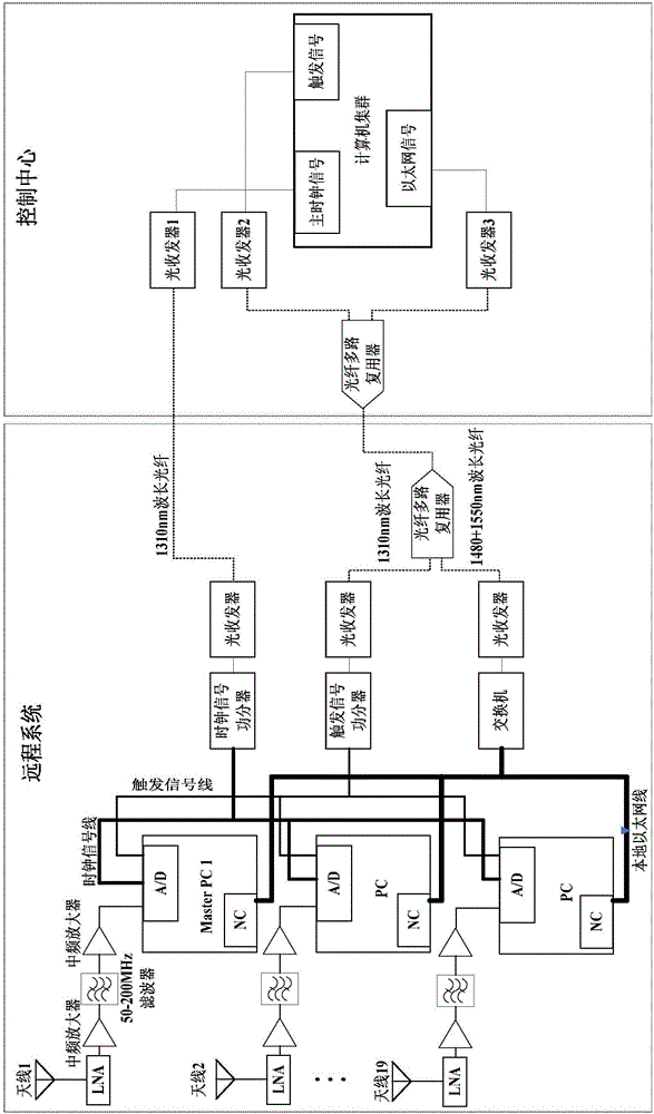
[0036] A low-frequency radio array digital beamforming system, such as figure 1 As shown, it is mainly composed of two parts: the control center and the remote system. In the present invention, the actual distance between the control center and the remote system is about 1200 meters.

[0037] The above-mentioned control center includes 1 control optical fiber multiplexer, 3 control optical transceivers and a computer cluster equipped with high-speed DSP and FPGA. The above-mentioned control center includes 1 control optical fiber multiplexer, 3 control optical transceivers and a computer cluster; wherein the computer cluster is provided with a main clock signal output interface, a trigger signal output interface and an Ethernet signal output interface; the main computer cluster Th...


PUM


Abstract

The present invention discloses a system and method for forming a low-frequency radio array digital beam. The system is mainly composed of a control center and a remote system. The method comprises the following steps: the control center transmits a clock signal, a trigger signal and an Ethernet signal to the remote system to complete data acquisition; and the remote system completes digital beam forming, wherein in a digital beam forming process, an FIR filter is adopted, and an FFT channel division and digital phase shifting method as well as a distributed stacking method are adopted. By adopting the system and method disclosed by the invention, problems of signal attenuation and inconsistent amplitudes/phases existing in analogue signal transmission can be avoided, and meanwhile, the calculation speed and accuracy of beam forming can be greatly increased, and beam pointing can be flexibly and accurately controlled.

Description

technical field [0001] The invention relates to the technical field of digital beam synthesis, in particular to a low-frequency radio array digital beam synthesis system and method. Background technique [0002] Square kilometer radio array (Square Kilometer Array, SKA) is the largest astronomical observation equipment built by human beings. The scientific goals that SKA expects to explore put forward very strict requirements on its performance indicators, which makes many cutting-edge radio observation technologies be adopted. Applied to SKA. As a major participating country of the SKA, China must be able to effectively process and analyze its scientific data after the official operation of the SKA. This goal cannot be separated from the in-depth understanding of many cutting-edge technologies among Chinese radio astronomy workers. Synthesis technology is one of the most important technologies. At the same time, in order to successfully develop the corresponding data proc...

Claims


Application Information

Patent Timeline
Patent Type & Authority Applications(China)
IPC IPC(8): H01Q3/34H01Q3/00H01Q21/00
CPCH01Q3/005H01Q3/34H01Q21/00
Inventor 劳保强安涛伍筱聪陆扬郭绍光
Owner SHANGHAI ASTRONOMICAL OBSERVATORY CHINESE ACAD OF SCI
Why Eureka
Try Eureka