
Intelligent dual-frequency antenna system

A dual-frequency antenna and antenna system technology, applied in the field of wireless communication, can solve the problems of unintelligence of the antenna, poor directional coverage, unstable terminal signal connection, etc., and achieve the effect of dynamic beam scanning

Active Publication Date: 2017-01-04
康凯科技(杭州)股份有限公司
View PDF5 Cites 17 Cited by
  • Summary
  • Abstract
  • Description
  • Claims
  • Application Information

AI Technical Summary

Problems solved by technology

However, the non-intelligence of the antenna itself has not been resolved
In addition, the gain of the omnidirectional antenna is generally low, and the directional coverage is poor. If there is no precise layout, the terminal signal connection is often unstable.

Method used


Image

  • Intelligent dual-frequency antenna system
  • Intelligent dual-frequency antenna system
  • Intelligent dual-frequency antenna system

Examples


Embodiment Construction

[0040] The detailed description of the present invention directly or indirectly simulates the operation of the technical solution of the present invention mainly through programs, steps, logic blocks, processes or other symbolic descriptions. In the ensuing description, numerous specific details are set forth in order to provide a thorough understanding of the present invention. Rather, the invention may be practiced without these specific details. These descriptions and representations herein are used by those skilled in the art to effectively convey the substance of their work to others skilled in the art. In other words, for the purpose of avoiding obscuring the present invention, well-known methods and procedures have not been described in detail since they have been readily understood.

[0041] Reference herein to "one embodiment" or "an embodiment" refers to a particular feature, structure or characteristic that can be included in at least one implementation of the pres...


PUM


Abstract

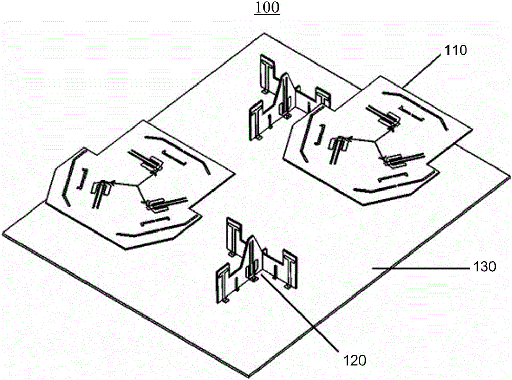
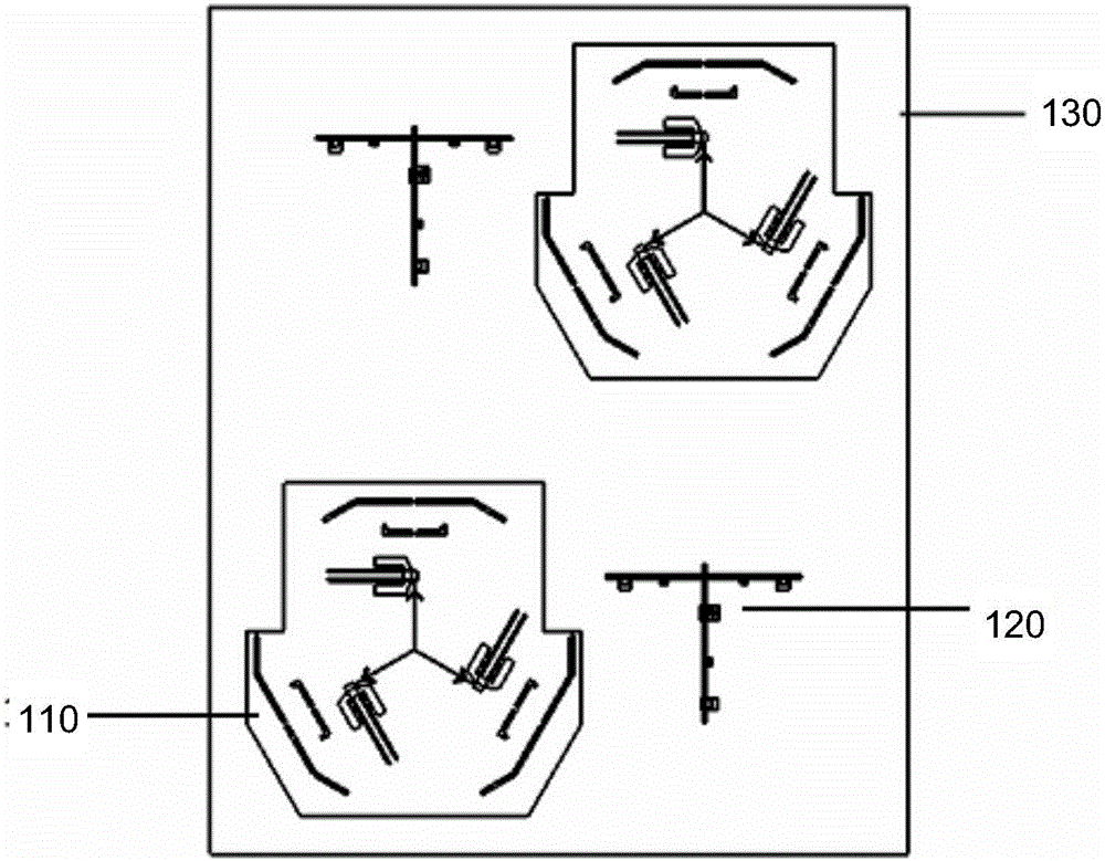
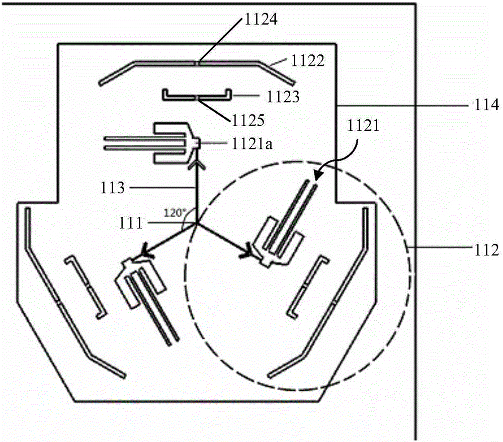
The invention discloses an intelligent dual-frequency antenna system including one or more dual-frequency antenna units. Each dual-frequency antenna unit comprises one or more dual-frequency oscillators, a first frequency band reflection unit and a second frequency band reflection unit on the outer side of the horizontally-polarized dual-frequency oscillator, a first frequency band switch unit corresponding to the first frequency band reflection unit, a second frequency band switch unit corresponding to the second frequency band reflection unit, and a control unit. The system controls on / off of each switch unit to change a radiation direction chart of each dual-frequency antenna unit. Compared with the prior art, the system can flexibly control the antenna radiation direction chart.

Description

[0001] 【Technical field】 [0002] The invention belongs to the field of wireless communication, and in particular relates to an intelligent dual-frequency antenna system. [0003] 【Background technique】 [0004] The antenna system is indispensable in the composition of the communication system. In the past wireless communication, a single antenna is used for the transmitting source and the receiving end respectively. This system is called SISO (Single Issue Single Receive). Such systems are prone to multipath effects which can cause problems. When the electromagnetic wave encounters obstacles such as hills, canyons, buildings, wires and cables, problems such as reflection, diffraction, and scattering will occur, so the electromagnetic wave will reach the destination through multiple paths. Delayed scattered signals cause signal fading, dropped calls at the edge (cliff effect) and intermittent reception (like picket fence pattern). In digital communication systems, such as th...

Claims


Application Information

Patent Timeline
IPC IPC(8): H01Q21/00H01Q21/24H01Q1/38H01Q3/44H01Q19/10H01Q19/12H01Q5/10
CPCH01Q1/38H01Q3/44H01Q5/10H01Q19/10H01Q19/12H01Q21/00H01Q21/24
Inventor 李鑫郑博信汪义兵沈骏赵辉
Owner 康凯科技(杭州)股份有限公司
Learn More