
IGBT-based hybrid high-voltage direct-current circuit breaker

A high-voltage DC and circuit breaker technology, applied in emergency protection circuit devices, electrical components, etc., can solve the problems of increasing the difficulty of IGBT series voltage equalization, solid-state switch damage, and turn-off failures, saving the number of IGBTs in series and reducing the number of series. Effect

Inactive Publication Date: 2017-01-04
TIANJIN UNIV
View PDF5 Cites 39 Cited by
  • Summary
  • Abstract
  • Description
  • Claims
  • Application Information

AI Technical Summary

Problems solved by technology

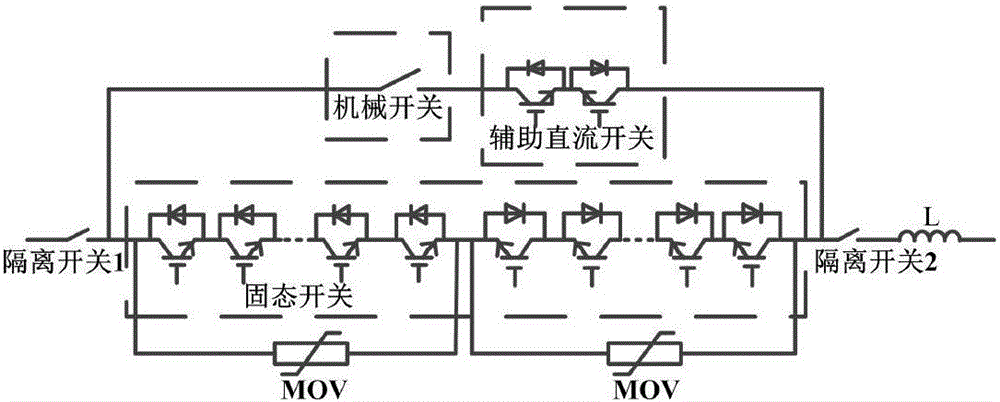
Its disadvantages are as follows: ①The solid-state switch is composed of a large number of IGBTs in series. As the voltage level increases, the number of IGBTs in series increases, which not only greatly increases the volume and production cost of the circuit breaker, but also increases the difficulty of IGBT series voltage equalization; ②In the process of breaking the short-circuit current, the voltage rise rate at both ends of the circuit breaker is too large, which may break down the mechanical switch and cause shutdown failure, and also cause damage to the solid-state switch

Method used


Image

  • IGBT-based hybrid high-voltage direct-current circuit breaker
  • IGBT-based hybrid high-voltage direct-current circuit breaker
  • IGBT-based hybrid high-voltage direct-current circuit breaker

Examples


Embodiment Construction

[0027] I topology

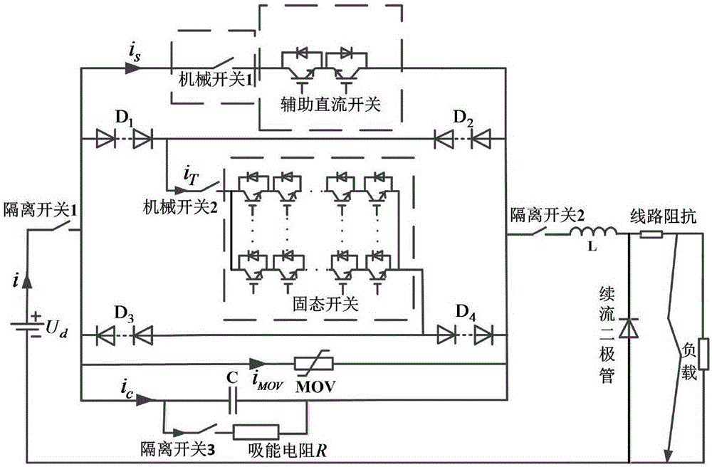
[0028] In order to solve the defects of the hybrid high-voltage DC circuit breaker developed by ABB, the present invention proposes a new type of hybrid high-voltage DC circuit breaker, whose topology is shown in the attached figure 2 As shown, its characteristics are as follows.

[0029] ① In the commutation branch, the diode valve bridge structure D 1 and D 4 Realize bidirectional turn-on and turn-off. Definition attached figure 2 The i direction is the forward direction of the current. When the current flows forward, the current of the commutation branch passes through D 1 → Mechanical Switch 2 → Solid State Switch → D 4 flow through; when the current flows in reverse, the commutation branch current passes through D 2 → Mechanical Switch 2 → Solid State Switch → D 3 flow past. Since a group of IGBTs can flow current in both forward and reverse directions, compared with ABB circuit breakers, half of the IGBTs are saved.

[0030] ② A mechanical ...


PUM


Abstract

The present invention relates to an IGBT-based hybrid high-voltage direct-current circuit breaker. The IGBT-based hybrid high-voltage direct-current circuit breaker comprises a current-carrying branch, a commutation branch, a buffer capacitor, an energy-absorbing branch and a lighting arrester which are connected in parallel with one another; the current-carrying branch comprises a first mechanical switch (1) and auxiliary direct-current switches, wherein the first mechanical switch (1) is connected in series with the auxiliary direct-current switches; the commutation branch comprises a diode bridge valve capable of realizing current bidirectional conduction; the commutation branch further comprises a second mechanical switch (2) and an IGBT valve which are connected in series with each other, wherein the IGBT valve is formed by connecting a plurality of IGBT branches in parallel; after current is transferred from the current-carrying branch to the commutation branch, the second mechanical switch (2) is controlled to be switched off, and after the second mechanical switch (2) achieve a preset rated opening distance, the IGBT valve is turned off; the energy-absorbing branch comprises third isolation switches and an energy-absorbing resistor which are in series connection; and a current limiting inductor is connected in series at the outlet of the circuit breaker. With the IGBT-based hybrid high-voltage direct-current circuit breaker of the invention adopted, the number of the solid-state switch IGBTs in series connection can be reduced, and the rising rate of voltage at two ends of the circuit breaker during a breaking process can be decreased.

Description

technical field [0001] The invention relates to the field of high-voltage direct current transmission, in particular to a high-voltage direct current circuit breaker. Background technique [0002] Compared with traditional AC power transmission, DC power transmission has the advantages of low line construction cost, low loss, simple power regulation, and no system synchronization operation stability problems, etc., and is widely used in ultra-high voltage, long-distance and high-power power transmission [1-3] . At the same time, with the demand for grid-connected renewable energy [4-5] and a voltage source converter [6] The rapid development of HVDC transmission at home and abroad is increasingly in-depth [7-9] . At present, most of the widely used DC systems are two-terminal systems. The reason is the lack of practical high-voltage DC circuit breakers. Flexible multi-terminal HVDC systems are more flexible and reliable, and are the development direction of HVDC systems...

Claims


Application Information

Patent Timeline
IPC IPC(8): H02H7/26
CPCH02H7/26H02H7/268
Inventor 张艳霞陶翔
Owner TIANJIN UNIV
Learn More