
Lifting device and lifting table

A lifting device and casing technology, which is applied to tables, tables with variable table heights, household appliances, etc., can solve the problems of high cost, complicated process, and high difficulty in disassembly and assembly, and achieve easy and soft lifting effects, low cost, and excellent structure simple effect

Pending Publication Date: 2017-01-11
ANHUI LAITE GAS SPRING CO LTD
View PDF7 Cites 32 Cited by
  • Summary
  • Abstract
  • Description
  • Claims
  • Application Information

AI Technical Summary

Problems solved by technology

[0003] In response to the above problems, a height-adjustable table has been slowly developed. Most of this height-adjustable table is fixed with screws. When adjusting, it is necessary to manually use tools to unscrew or loosen the screws, and then it can be adjusted again. The height is difficult to disassemble and assemble, the process is complicated and laborious; and the height of each adjustment has a large limit, the adjustable distance is relatively large, and the degree of automation is not high. The height of the table cannot be adjusted automatically to meet the requirements provided The experience of digital automation
[0004] In order to improve the automation of table height adjustment, most of the lifting tables on the market use motors to control the lifting, the cost is relatively high, and it needs to use electric energy when it needs to be used, which increases the cost of use.

Method used


Image

  • Lifting device and lifting table
  • Lifting device and lifting table
  • Lifting device and lifting table

Examples


Embodiment Construction

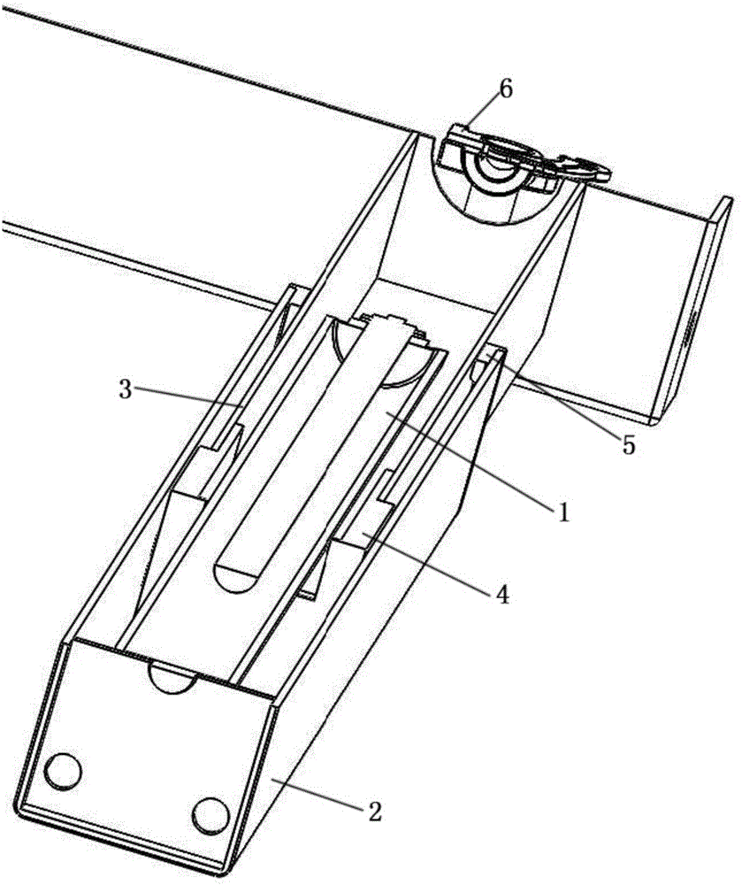
[0029] Such as figure 1 As shown, the lifting device of the present invention includes: a spring 1, a first bushing 2, a second bushing 3, a rolling friction assembly 4, a sliding friction assembly 5, The connection component 6 and the control component 7 are described in detail below for each part and the relationship between them:

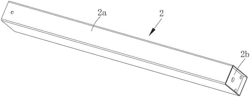
[0030] Such as figure 1 and figure 2 As shown, the spring 1 is preferably a gas spring. One end of the spring 1 is located in the first sleeve 2 and fixed to one end of the first sleeve 2, the first sleeve 2 is composed of a first square tube 2a and a bottom plate 2b, and the bottom plate 2b is fixed on the first sleeve 2 At one end, a part of the spring 1 is located in the first square tube 2a, and one end of the spring 1 is fixedly connected with the bottom plate 2b.

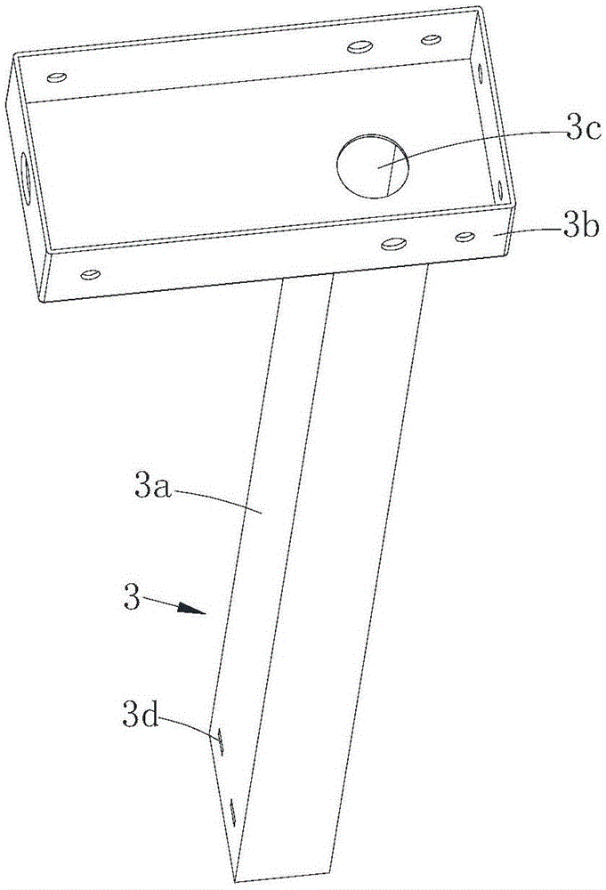
[0031] Such as figure 1 and image 3 As shown, one end of the second sleeve 3 is inserted into the first sleeve 2 from the other end of the first sleeve 2, the second slee...


PUM


Abstract

The invention discloses a lifting device. The lifting device comprises a spring, a first sleeve, a second sleeve, a connecting assembly and a control assembly, wherein the spring is used for providing maintaining action force after lifting and uses a fluid as a damping medium; one end of the spring is located in the first sleeve and fixed with one end of the first sleeve; one end of the second sleeve is inserted into the first sleeve from the other end of the first sleeve, and a guide assembly for facilitating lifting of the second sleeve is arranged on the first sleeve and / or the second sleeve; the connecting assembly is arranged at the other end of the second sleeve, and the other end of the spring penetrates the second sleeve to be connected with the connecting assembly; the control assembly is connected with a control part, used for controlling flowing of the fluid, in the spring after being connected with the connecting assembly. The lifting device has the effects that the lifting device can be lifted anytime anywhere and is safe, reliable, free of energy consumption and lower in cost compared with an electric lifting table.

Description

technical field [0001] The invention relates to a lifting device and a lifting table. Background technique [0002] As a daily necessities, the table is commonly used in life, work and school study. The general table is usually composed of a table top and table legs fixedly connected, and the length of the table legs is also fixed, so that the height of the entire table top is fixed. regulated. With the different application environments and the application needs of different groups of people, the requirements for the height diversity, automation and comfort of the table are getting higher and higher. [0003] In response to the above problems, a height-adjustable table has been slowly developed. Most of this height-adjustable table is fixed with screws. When adjusting, it is necessary to manually use tools to unscrew or loosen the screws, and then disassemble and assemble to adjust. The height is difficult to disassemble and assemble, the process is complicated and labori...

Claims


Application Information

Patent Timeline
Patent Type & Authority Applications(China)
IPC IPC(8): A47B9/10A47B9/20A47B91/02
CPCA47B9/10A47B9/20A47B91/02A47B2200/0059A47B2200/0053
Inventor 陶声荣
Owner ANHUI LAITE GAS SPRING CO LTD
Learn More