Conveying and lifting mechanism for laser-cut steel plates

A laser cutting and steel plate technology, applied in the direction of conveyor objects, transportation and packaging, can solve the problems of inability to meet the height, reduce efficiency, affect use, etc., and achieve the effect of reducing manual labor, good effect and high efficiency

Inactive Publication Date: 2017-01-11
DONGGUAN LIANZHOU INTPROP OPERATION MANAGEMENT CO LTD
View PDF10 Cites 12 Cited by
  • Summary
  • Abstract
  • Description
  • Claims
  • Application Information

AI Technical Summary

Problems solved by technology

[0004] After the laser-cut steel plate is cut, it needs to be placed on a fixed platen for manual polishing, and it needs to be fixed manually with bolts on the platen, the effect is not ideal
greatly reduce the efficiency when using
[0005] Moreover, the existing fixed platen cannot be adjusted up and down, so that it cannot meet the height required by the user, which affects the use

Method used


Image

  • Conveying and lifting mechanism for laser-cut steel plates
  • Conveying and lifting mechanism for laser-cut steel plates
  • Conveying and lifting mechanism for laser-cut steel plates

Examples


Embodiment Construction

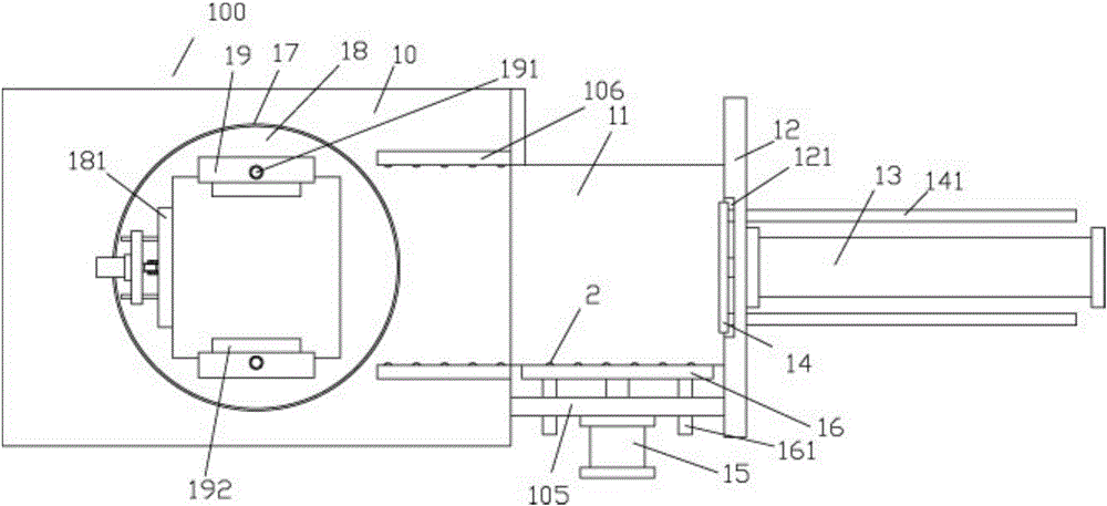
[0025] Examples, see e.g. Figure 1 to Figure 4 As shown, a laser cutting steel plate conveying and lifting mechanism includes a frame 100, the middle part of the right side of the top plate 10 of the frame 100 is fixed with a feed guide plate 11, and the right side of the feed guide plate 11 is fixed with a connecting support plate body 12, the middle part of the right side of the connection support plate body 12 is fixed with a pusher cylinder 13, the push rod of the pusher cylinder 13 passes through the connection support plate body 12 and is fixed with a push plate 14, the machine at the place ahead of the feed guide plate 14 The frame 100 is provided with a side wall support cylinder 15, and a side support plate 16 is fixed on the push rod of the side wall support cylinder 15, and the side support plate 16 is close to the feeding guide plate 14;

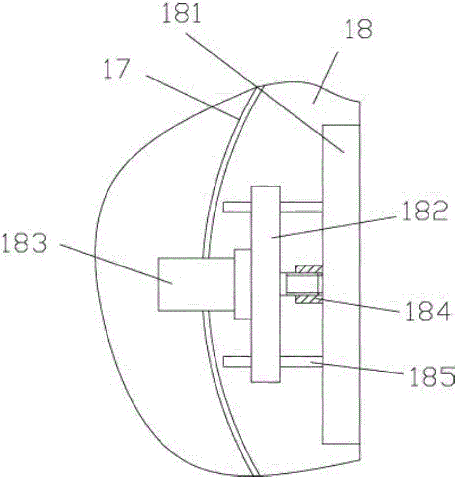
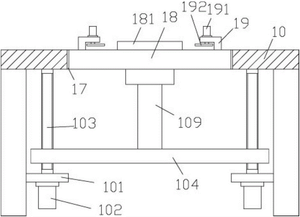
[0026] The middle part of the top plate 10 has a circular vertical through hole 17, a circular lifting plate 18 is inserted in...


PUM


Abstract

The invention discloses a conveying and lifting mechanism for laser-cut steel plates. The conveying and lifting mechanism for the laser-cut steel plates comprises a rack. A feeding guide plate is fixed to the middle of the right side of a top plate of the rack. A connecting and supporting plate is fixed to the right side of the feeding guide plate. A pushing air cylinder is fixed to the middle of the right side of the connecting and supporting plate. A push rod of the pushing air cylinder penetrates through the connecting and supporting plate and is fixedly provided with a pushing plate. A side wall supporting air cylinder is arranged in the position, in front of the feeding guide plate, of the rack. A side supporting plate is fixed to a push rod of the side wall supporting air cylinder, and the side supporting plate is close to the feeding guide plate. A round vertical through hole is formed in the middle of the top plate, and a round lifting plate is inserted in the round vertical through hole in a sleeved mode. The conveying and lifting mechanism is installed at an automatic polishing device, can automatically convey the steel plates placed on the feeding guide plate and lift the steel plates to the polishing portion in clamping and fixing modes so that the steel plates can be polished, and is high in efficiency and good in effect, the situation that workers perform fixation with bolts is avoided, and the manual labor quantity is greatly reduced.

Description

[0001] Technical field: [0002] The invention relates to the technical field of laser processing equipment, and more specifically relates to a conveying and lifting mechanism for laser-cut steel plates. [0003] Background technique: [0004] After the laser-cut steel plate is cut, it needs to be placed on a fixed platen for manual polishing, and its fixing on the platen needs to be manually fixed by bolts, which is not ideal. The efficiency during use is greatly reduced. [0005] Moreover, the existing fixed platen cannot be adjusted up and down, so that it cannot meet the height required by the user, which affects the use. [0006] Invention content: [0007] The purpose of the present invention is to overcome the deficiencies of the prior art and provide a laser-cut steel plate conveying and lifting mechanism, which is installed at the automatic polishing equipment, and can automatically transport and clamp and fix the steel plate placed on the feeding guide plate to the ...

Claims


Application Information

Patent Timeline
Patent Type & Authority Applications(China)
IPC IPC(8): B65G47/82B65G47/74
CPCB65G47/82B65G47/74
Inventor 李风浪李舒歆
Owner DONGGUAN LIANZHOU INTPROP OPERATION MANAGEMENT CO LTD
Why Eureka
Try Eureka