
Rotation device

A technology of slewing device and slewing shaft, which is applied in the direction of cranes, etc., can solve the problems of high cost, low efficiency, unstable spring work, etc., and achieve the effects of improving the stress condition, prolonging the service life, and reducing costs

Inactive Publication Date: 2017-01-11
SICHUAN HONGHUA PETROLEUM EQUIP
View PDF10 Cites 2 Cited by
  • Summary
  • Abstract
  • Description
  • Claims
  • Application Information

AI Technical Summary

Problems solved by technology

However, due to the complex structure of the spring, the size is larger, the weight is heavier, and the cost is higher; at the same time, the spring will cause unstable work due to fatigue, resulting in low efficiency

Method used


Image

  • Rotation device
  • Rotation device
  • Rotation device

Examples


Embodiment

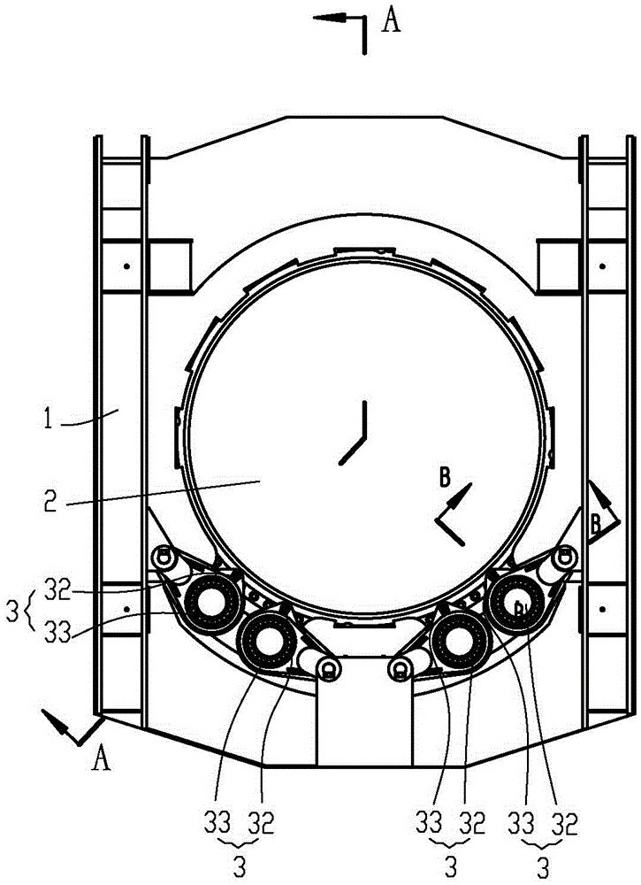
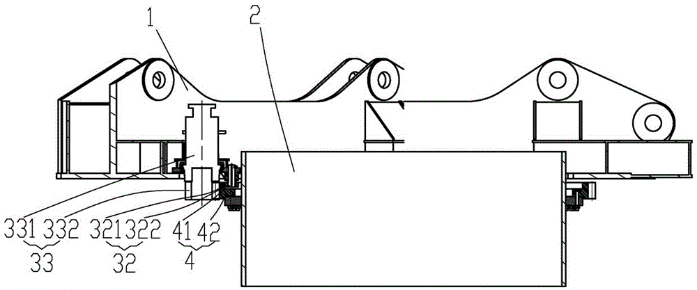
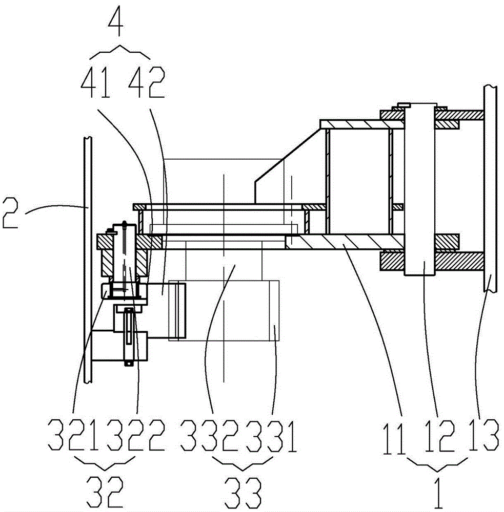
[0028] Such as Figure 1-3 A rotary device shown includes a support device 1, a rotary shaft 2, a drive device 3, a large gear 4, and the large gear 4 is fixedly connected to the rotary shaft 2, the rotary shaft 2 is connected to the support device 1 in rotation, and the drive device 3 is connected to the support device 1 is fixedly connected, and the driving device 3 is connected with the bull gear 4.

[0029] The bull gear 4 includes a gear body 42 and a peripheral surface 41 .

[0030] The driving device 3 includes a reduction gear 33 and a roller mechanism 32 .

[0031] The reduction gear 33 includes a reduction mechanism 332 and a pinion 331 .

[0032] The roller mechanism 32 includes a support mechanism 322 and a roller 321 .

[0033] The supporting device 1 includes a supporting seat 13 , a driving seat 11 and a connecting shaft 12 .

[0034] The driving device 3 is fixedly connected with the driving support 11 ; the driving support 11 is connected with the support ...


PUM


Abstract

The invention relates to the field of engineering equipment, and specifically relates to a rotation device. The rotation device comprises a support device, a drive device, a rotation device and a large gear, wherein the drive device is connected with the support device; the rotation device is connected with the support device; the large gear is connected with the rotation device; the large gear comprises a circumferential surface; the drive device comprises a pinion and a rolling mechanism; the pinion is engaged with the large gear; and the rolling mechanism moves along the circumferential surface of the large gear. In this way, instable working caused by separation of the pinion and the large gear due to the engagement can be avoided, an impact is avoided, a weight is reduced, the stress condition of the engagement of the pinion and the large gear is improved, the service life is prolonged, and the purposes of reducing cost and increasing efficiency are achieved.

Description

technical field [0001] The invention relates to the field of engineering equipment, in particular to a slewing device. Background technique [0002] In the lifting equipment that needs to be turned to work, it needs to be driven to turn, which requires a turning device. [0003] When the lifting tonnage is small, the use of slewing support and internal drive can achieve the purpose. When the lifting weight is large, the slewing support cannot meet the requirements, and an externally driven slewing device is required. Usually, the externally driven slewing device will cause the pinion to deviate from the bull gear due to the force generated by the meshing of the pinion and the bull gear. At this time, a spring is used to ensure the meshing of the bull gear and the pinion. However, due to the complex structure of the spring, the size is larger, the weight is heavier, and the cost is higher; at the same time, the spring will cause unstable work due to fatigue, resulting in lo...

Claims


Application Information

Patent Timeline
Patent Type & Authority Applications(China)
IPC IPC(8): B66C23/84
CPCB66C23/84
Inventor 秦皓李健肖勇张庆明
Owner SICHUAN HONGHUA PETROLEUM EQUIP
Learn More