Climate sensing control device for glass structure building

A technology of induction control and induction device, which is applied in the directions of buildings, building components, building structures, etc., can solve the problems of large range, insufficient convenience, and elevation of roller shutters, and achieve the effect of comfortable use.

Active Publication Date: 2017-01-11
FOSHAN RONGGAO INTELLIGENCE TECH
View PDF6 Cites 19 Cited by
  • Summary
  • Abstract
  • Description
  • Claims
  • Application Information

AI Technical Summary

Problems solved by technology

Therefore, the user needs to frequently switch the window and switch the roller shutter motor according to the weather conditions during use, which is not convenient for use.
[0004] The structure of the existing wind detection device is generally that the wind blade drives the coil to rotate in the magnetic field to generate a current, and the magnitude of the wind force is judged according to the magnitude of the generated current. However, when this method is used in buildings, the cost will be relatively high. , Circuit more complex problems
[0005] Another example is that under the external light conditions, there will be a greenhouse effect, and the internal temperature will gradually rise, causing users to feel stuffy. Therefore, existing buildings are generally equipped with manual sunshades on the roof and on each wall. When the sun is strong, you can put down the sunshade to resist the direct sunlight, but the sun generally shines on part of the surface of the building from a certain direction, and the direction of the sun will change at different times of the day, so users need to Frequently close the sunshade on the surface to be irradiated and open the sunshade not to be irradiated, so as to keep enough light in the room for use without being irradiated violently, which is inconvenient to use
[0006] According to the existing technical conditions, there are several ways to solve the above problems. The first one is to use silver

Method used


Image

  • Climate sensing control device for glass structure building
  • Climate sensing control device for glass structure building
  • Climate sensing control device for glass structure building

Examples


Embodiment Construction

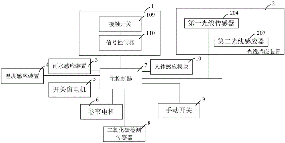
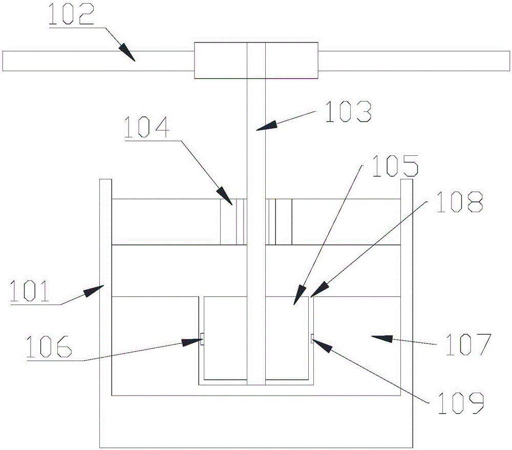
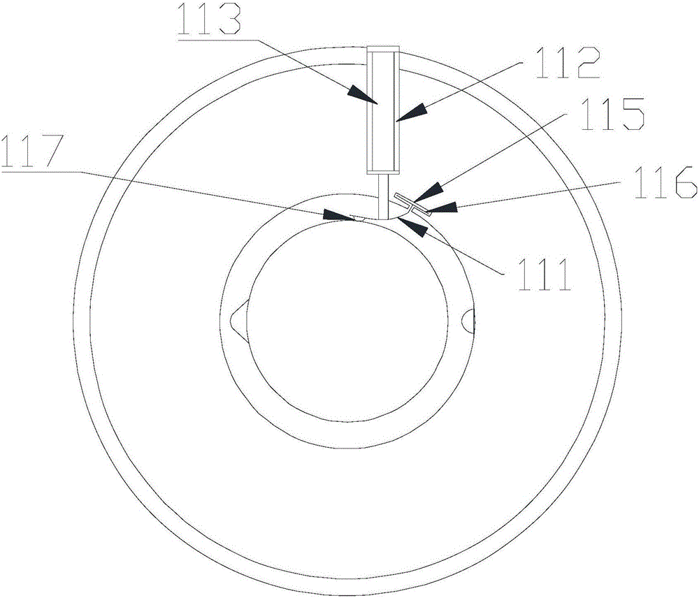
[0032] Such as Figure 1-Figure 4 As shown, embodiments of the present invention include

[0033] A wind sensor device installed outside the building to sense the external wind force and generate a signal according to the wind force 1,

[0034] A light sensing device installed outside the building to sense the intensity of external light and generate a signal 2,

[0035] A rainwater sensing device installed outside the building to sense rainwater conditions and generate signals according to rainwater conditions 3.

[0036] Temperature sensing device installed in the building 4,

[0037] The switch window motor 5, which is installed on the window and is used to drive the window switch,

[0038] Installed on the window, the user drives the roller shutter motor 6 to retract and retract the curtain

[0039] Connect with wind sensor 1, light sensor 2, rain sensor 3, temperature sensor 4, switch window motor 5, roller shutter motor 6, according to wind sensor 1, light sensor 2, ...


PUM


Abstract

The invention relates to a building indoor environment adjusting control system, in particular to a climate sensing control device for a glass structure building. The device comprises a wind sensing device arranged outside the building, a light sensing device arranged outside the building, a rainwater sensing device arranged outside the building, a temperature sensing device arranged inside the building, a window opening and closing motor installed on a window for driving the window to be opened and closed, a roller blind motor arranged on the window for driving a roller blind to be rolled and unrolled, and a master controller connected with the wind sensing device, the light sensing device, the rainwater sensing device, the temperature sensing device, the window opening and closing motor and the roller blind motor. The wind sensing device is adopted on the building for sensing the outside wind strength, window opening and closing control can be automatically carried out, the working state of the roller blind motor is controlled, influences of outside strong wind, rainwater and sunlight on the indoor environment are avoided, and a user can use the device more comfortably.

Description

technical field [0001] The invention relates to a building indoor environment regulation and control system, in particular to a glass structure building climate induction control device. Background technique [0002] With the development of modern architectural decoration design, in order to make reasonable use of space, buildings are often set up in the courtyards of some residences or on the roofs of villas. Buildings are independent architectural forms that use glass or other transparent materials as the main body. The purpose is that the user located in the building room can not only directly use the external light, but also avoid the influence of wind, rain, and snow on the user, so that the user's use is more comfortable and comfortable. In the use of the building, considering that the building is a space with limited space and transparency, the comfort level of its interior use is closely related to the external climate environment. [0003] For example, under extern...

Claims


Application Information

Patent Timeline
IPC IPC(8): E05F15/71E05F15/70E05F15/603E06B9/68
CPCE05F15/603E05F15/70E05F15/71E05Y2400/44E05Y2900/148E06B9/68E06B2009/6818E06B2009/6827E06B2009/6863
Inventor 王海波
Owner FOSHAN RONGGAO INTELLIGENCE TECH
Why Eureka
Try Eureka