Engine air inlet pipe and engine system

A technology of engine and air intake pipe, which is applied in the direction of engine components, machine/engine, charging system, etc., can solve the problems of safe driving of the car and affect the driving performance of the car, achieve long service life, easy to realize transformation, ensure stability and safety effect

Inactive Publication Date: 2017-01-11
QOROS
View PDF6 Cites 3 Cited by
  • Summary
  • Abstract
  • Description
  • Claims
  • Application Information

AI Technical Summary

Problems solved by technology

In addition, these moisture can also enter the air intake system through the main air inlet, which will also affect the driving performance of the car and cause problems in the safe driving of the car

Method used


Image

  • Engine air inlet pipe and engine system
  • Engine air inlet pipe and engine system
  • Engine air inlet pipe and engine system

Examples


Embodiment Construction

[0058] The engine intake pipe and the engine system of the present invention will be further described in detail in conjunction with the drawings and specific embodiments below, but the detailed description does not constitute a limitation of the present invention.

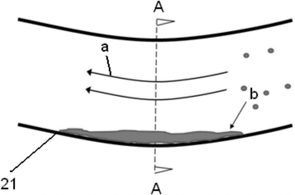
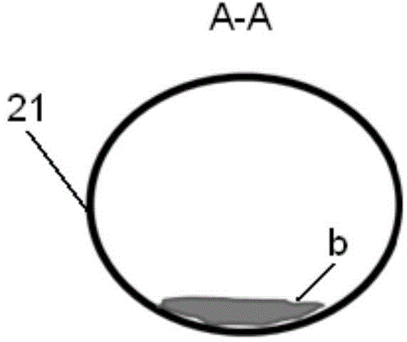
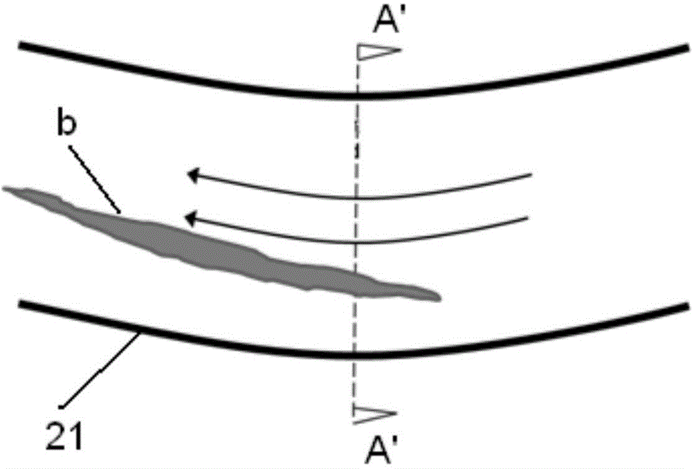
[0059] Figure 5 to Figure 8 The structure and state of the engine intake pipe in an embodiment of the present invention are respectively shown.

[0060] like Figure 5 to Figure 8 As shown, along the flow direction X of gas a, the engine intake pipe 10 has an inlet port 11 and an outlet port 12. Gas a enters from the inlet port 11 along with the flow direction X and leaves from the outlet port 12. The bottom of the air pipe 10 is continuously provided with an elastic portion 13, which can protrude inward or outward according to the pressure difference between the inside and outside of the engine intake pipe 10, for example, when the engine is working, When the trachea is inhaled, the air pressure inside the air...


PUM


Abstract

The invention discloses an engine air inlet pipe. An elastic part is arranged at the bottom of the engine air inlet pipe. The elastic part generates form changes according to the changes of the difference of the pressure inside and outside the engine air inlet pipe, and crushing force is accordingly applied to ice blocks accumulated on the elastic part. The invention further discloses an engine system provided with the engine air inlet pipe. The engine air inlet pipe can effectively crush the ice blocks accumulated to be in large size into small-size ice blocks, and therefore the phenomenon that normal work of other parts of an engine is hindered when the kind of ice blocks get away from the air inlet pipe is avoided, and the running stability and safety of the engine are better ensured. The engine system is good in running stability, high in safety coefficient and long in service life.

Description

technical field [0001] The invention relates to a gas delivery pipeline, in particular to an intake pipeline for an engine. The invention also relates to an engine system. Background technique [0002] The combustion process of the automotive internal combustion engine will cause some gases (including combustion products and vaporized lubricating oil, collectively referred to as blow-by gas) to enter the crankcase by bypassing the plunger ring. These gases are eventually exhausted from the upper area of ​​the engine into the intake system through the Positive Crankcase Ventilation (PVC) system. This blow-by gas is mixed with the regular air passing through the engine and burned in the subsequent combustion process to ensure that the residual, unburned hydrocarbons in the blow-by gas are fully burned, thereby reducing harmful pollutants of the engine. The blow-by gas includes large amounts of water vapor, which is a major by-product of combustion. [0003] A positive crank...

Claims


Application Information

Patent Timeline
Patent Type & Authority Applications(China)
IPC IPC(8): F02M35/104
Inventor 彦斯·贝肯丁力·罗伯特胡壮丰
Owner QOROS
Why Eureka
Try Eureka