Ground positioning marking device for aerial shooting measurement of middle/low-altitude aircraft

A low-altitude aircraft and ground technology, applied in the directions of measuring devices, measuring rulers, measuring point markings, etc., can solve the problem of difficult to find marking points, etc., and achieve the effects of wide practicability, convenient use and improved accuracy

Inactive Publication Date: 2017-01-11
XINJIANG NORMAL UNIVERSITY
View PDF5 Cites 7 Cited by
  • Summary
  • Abstract
  • Description
  • Claims
  • Application Information

AI Technical Summary

Problems solved by technology

[0004] In view of the deficiencies and existing problems of the current state of the art, especially the technical defect that it is difficult to find marker points during the aerial photography measurement of the existing medium and low altitude aircraft, the present invention provides a ground positioning marking device suitable for the aerial photography measurement of the medium and low altitude aircraft. Compared with the prior art, the present invention provides a ground positioning marking device suitable for aerial photography of low- and medium-altitude aircraft, which is simple in structure, easy to use, clearly visible in aerial photography, easy to identify, and improves the accuracy of aerial topographic maps. The center points of multiple local positioning mark devices are used as the photo control points of aircraft aerial photography measurement to measure the plane coordinates and height of the control points, and the precise and delicate three-dimensional shape of the measured object can be obtained, which has wide practicability

Method used


Image

  • Ground positioning marking device for aerial shooting measurement of middle/low-altitude aircraft
  • Ground positioning marking device for aerial shooting measurement of middle/low-altitude aircraft
  • Ground positioning marking device for aerial shooting measurement of middle/low-altitude aircraft

Examples


Embodiment 1

[0026] Embodiment 1: Ground positioning marking device suitable for aerial photography measurement of low- and medium-altitude aircraft

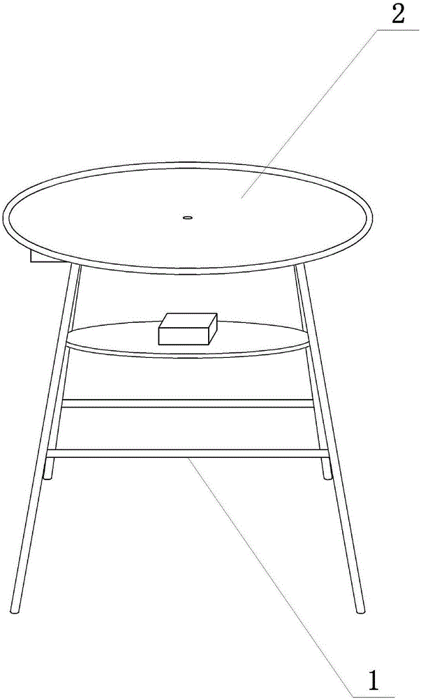
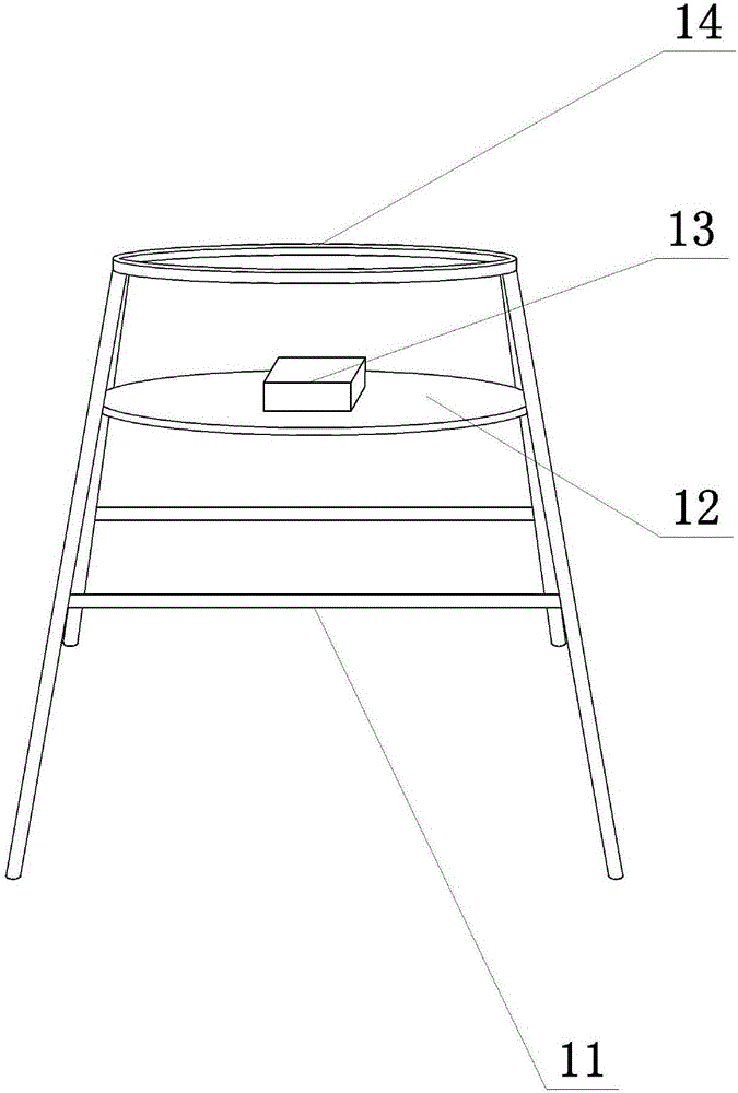
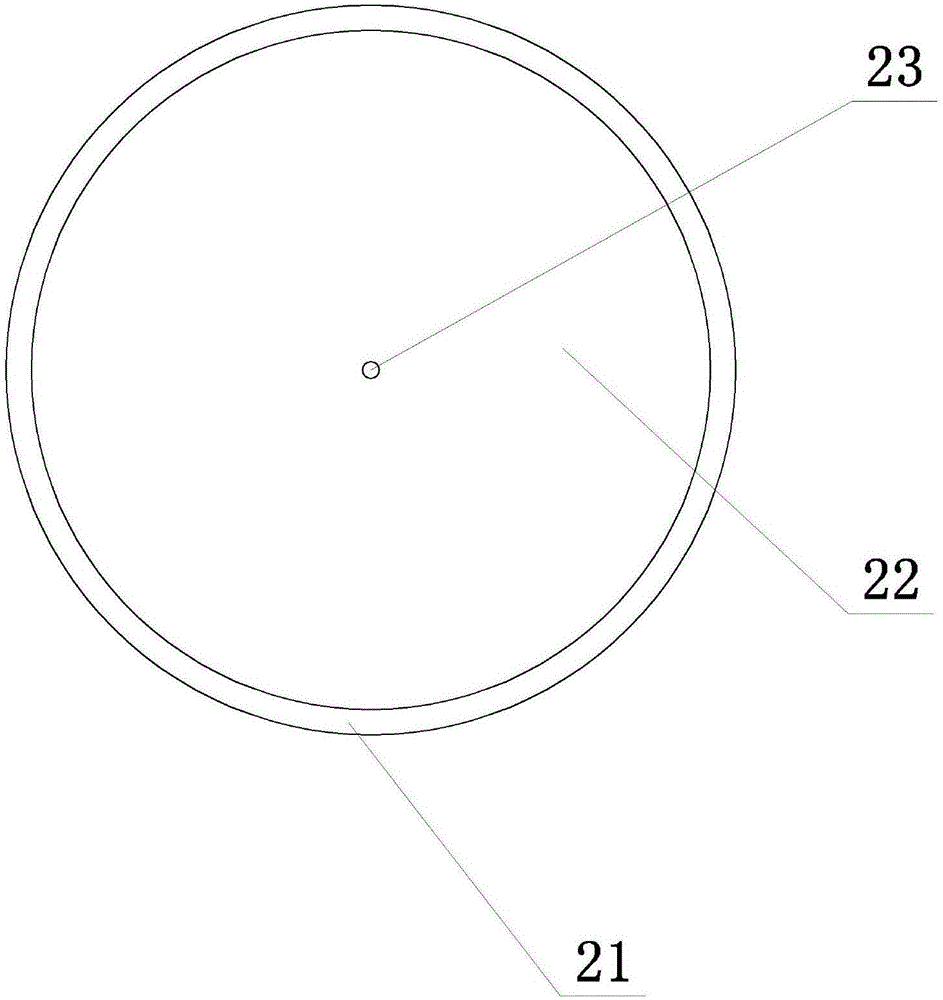
[0027] See attached Figure 1-4 , a ground positioning mark device suitable for aerial photography measurement of low- and medium-altitude aircraft provided by the present invention, comprising a bracket (1) and a positioning plate (2), the bracket (1) includes a leg (11) and a mounting ring (14), the installation The lower part of the ring (14) is movably connected with the outrigger (11), and the outrigger (11) is in the shape of a folded ladder. The positioning disc (2) includes a disc body (22), wrapping (21) and positioning core (23), and the disc body (22) is cylindrical, and the wrapping (21) is in the shape of a ring, and the wrapping (21) covers the disc body (22) for a week, and the positioning core (23) is set at the center of the disc body (22), below the disc body (22) An installation groove (25) is provided, and the installati...

Embodiment 2

[0031] Embodiment 2: Optimization of the ground positioning marking device suitable for aerial photography measurement of low- and medium-altitude aircraft

[0032] In order to implement the technical solution of the present invention and provide a ground positioning marking device suitable for aerial photography measurements of low- and medium-altitude aircraft, the preferred maximum diameter of the disc body (22) is 40 mm, and the upper surface of the disc body (22) is provided with a black paint coating layer, and the black paint It can reduce specular reflection, increase diffuse reflection, and have good light absorption.

[0033] In the present invention, it is preferred that the radial length of the wrapping (21) covering the disc body (22) is 3 mm, and the outer surface of the wrapping (21) is provided with a tinfoil layer, which has good reflective properties.

[0034] The preferred fixing rope (26) of the present invention adopts a rubber rope.

[0035] The preferre...

Embodiment 3

[0039] Embodiment 3: The application of the ground positioning marking device suitable for aerial photography measurement of low- and medium-altitude aircraft

[0040] When applying a ground positioning marking device suitable for aerial photography measurement of medium and low-altitude aircraft provided by the present invention, multiple sets of this device are placed near the aerial photography site, and the placement position of the bracket (1) is adjusted to ensure that the spirit level (13) is level and then the bracket is fixed (1), after igniting the insect repellent box (24), the aircraft can take aerial photography, and use the positioning core (23) as a photo control point by capturing the positioning core (23); when taking aerial photography in a place with lush forests, the positioning plate (2) can be disassembled and used alone. Rope (26) fixes positioning disc (2) on the tree branches and leaves, and after lighting the insect repelling box (24), the aircraft can...


PUM

PropertyMeasurementUnit
Diameteraaaaaaaaaa
Radial lengthaaaaaaaaaa
Diameteraaaaaaaaaa

Abstract

The invention discloses a ground positioning marking device for aerial shooting measurement of a middle / low-altitude aircraft. The ground positioning marking device comprises a bracket and a positioning plate, wherein the bracket comprises a support leg and a mounting ring; the lower side of the mounting ring is moveably connected with the support leg; the support leg is of a foldable ladder shape; the positioning plate comprises a plate body, a binding edge and a positioning core; the plate body is of a cylindrical shape; the binding edge is of circular shape; the binding edge is circularly covered on the plate body; the positioning core is arranged at the center of the plate body; a mounting groove is arranged under the plate body; the mounting groove of the positioning plate is connected with the mounting ring on the bracket through a clamping slot. The ground positioning marking device has a simple structure and is convenient to use; the aerial photo is clear and easy to identify; the precision of aerial surveying topographic map is increased; the center points of a plurality of ground positioning marking devices are utilized as the control points of the photos aerially shot by the aircraft to measure the plane coordinates and height of the control points; the accurate fine three-dimensional form of a measured object can be acquired; the practicability is wide.

Description

technical field [0001] The invention belongs to the technical field of aircraft aerial photography measurement, and more specifically, the invention relates to the technical field of an aircraft aerial photography measurement positioning device. Background technique [0002] Aerial photography measurement, also known as aerial photogrammetry, refers to the operation of continuously taking pictures of the ground with aerial photography instruments on the aircraft, combining the steps of ground control point measurement, mapping and three-dimensional mapping to draw topographic maps. Aerial photogrammetry can be used in fields such as field micro-geomorphology research, forest survey, archaeology, and cultural relic restoration. The operation of aerial photogrammetry involves the joint measurement of photo control points. The photo control points are generally the marker points arranged on the ground before the aerial photography. You can also choose obvious ground object poin...

Claims


Application Information

Patent Timeline
IPC IPC(8): G01C15/06G01C15/08G01C11/00
CPCG01C11/00G01C15/06G01C15/08
Inventor 来风兵黄铁成贾翔陈孟禹汪东邹佳秀林家煌尹小英李丽许超宗侯博展
Owner XINJIANG NORMAL UNIVERSITY
Why Eureka
Try Eureka