Double vibration sensor-based rotor imbalance vibration response identification method

A rotor unbalance and vibration response technology, applied in the field of rotor dynamic balance, can solve problems such as rotor unbalance vibration response, anisotropic rotor system unbalance vibration response, etc., and achieve the effect of improving dynamic balance accuracy

Inactive Publication Date: 2017-01-11
ZHEJIANG UNIV
View PDF5 Cites 8 Cited by
  • Summary
  • Abstract
  • Description
  • Claims
  • Application Information

AI Technical Summary

Problems solved by technology

[0003] The purpose of the present invention is to solve the problem that the conventional single vibration sensor cannot effectively identify the unbalanced vibration response of the rot

Method used


Image

  • Double vibration sensor-based rotor imbalance vibration response identification method
  • Double vibration sensor-based rotor imbalance vibration response identification method
  • Double vibration sensor-based rotor imbalance vibration response identification method

Examples


Embodiment Construction

[0017] The present invention will be further described below in conjunction with drawings and embodiments.

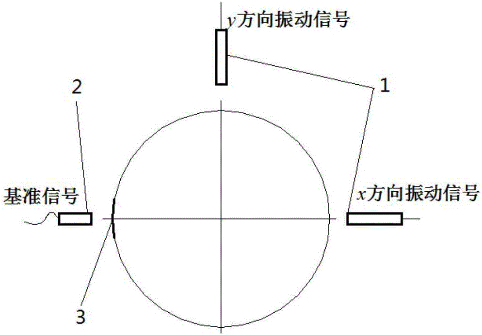
[0018] Step 1. Install vibration sensors of the same type in two mutually perpendicular radial x and y directions on the measurement section of the rotor bearing seat, and measure the vibration signal in the x direction and the vibration signal in the y direction Stick a reflective paper on the rotor shaft, use the speed sensor to face the reflective paper, and measure the reference signal s(t) of the rotor.

[0019] Step 2. Convert the vibration signal in the x direction Calculate the cross-correlation with the reference signal s(t) to obtain the frequency conversion vibration signal in the x direction x(t)=A cos(ωt+α); the vibration signal in the y direction Calculate the cross-correlation with the reference signal s(t) to obtain the y-direction frequency vibration signal y(t)=B cos(ωt+β)

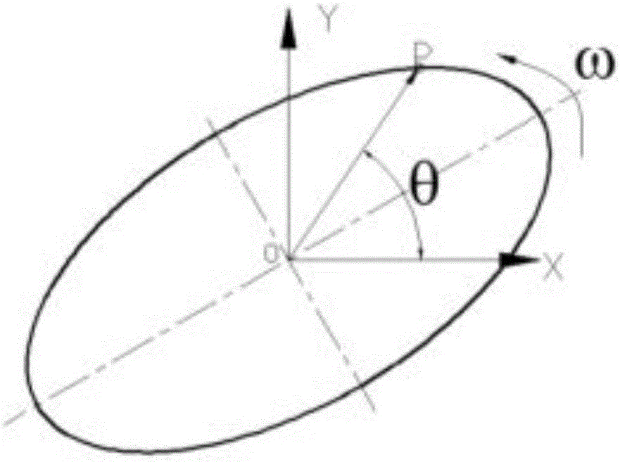
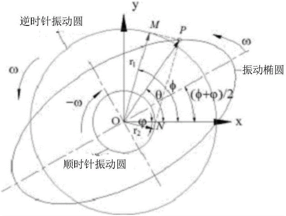
[0020] Step 3. Combining x(t) and y(t) into a vibrating ellipse can be ...


PUM


Abstract

The invention discloses a double vibration sensor-based rotor imbalance vibration response identification method which comprises the following steps: a, vibration sensors of the same model are mounted on two random axial directions x and y that are perpendicular to each other on a measurement cross section of a rotor bearing seat, a piece of light reflection paper is pasted on a rotor shaft, a rotation speed sensor is positioned opposite to the light reflection paper, and the vibration sensors in the direction x and the direction y and the rotation speed sensor are subjected to vibration signal and reference signal sampling operation; b, cross correlation technologies are used for extracting amplitude and phase positions of rotation frequency vibration in the direction x and the direction y; c, rotation frequency vibration signals in the direction x and the direction y are fused into a vibration ellipse; d, the vibration ellipse is broken into a clockwise vibration circle and an anticlockwise vibration circle, and the anticlockwise vibration circle is used for representing imbalanced vibration response. The double vibration sensor-based rotor imbalance vibration response identification method can help solve a problem that imbalanced vibration response of an anisotropy rotor system in a circumferential direction of kinetics parameters such as rigidity, damping and the like cannot be effectively identified via a single vibration sensor.

Description

technical field [0001] The invention belongs to the technical field of rotor dynamic balance, and in particular relates to a rotor unbalanced vibration response identification method based on dual vibration sensors. Background technique [0002] Fans, pumps, centrifuges, steam turbines and other rotating machinery are widely used in steel, cement, electric power, chemical industry, aviation, automotive environmental protection and other industries, and play an important role in modern industry. According to relevant statistics, more than 2 / 3 of the vibration faults of rotating machinery are mainly caused by rotor imbalance. Unbalance will cause disturbance and internal stress of the rotor, cause vibration and noise of the machine, accelerate the wear of bearings and shaft seals, and reduce the working efficiency of the machine. In order to reduce vibration and prolong the service life of the machine, the rotor must be dynamically balanced. Dynamic balance technology is an ...

Claims


Application Information

Patent Timeline
IPC IPC(8): G01M1/16
CPCG01M1/16
Inventor 张志新万可达曾文亮
Owner ZHEJIANG UNIV
Why Eureka
Try Eureka